Functional Diagrams form part of diagrams used In
Instrumentation. In our previous articles, we looked at Process Flow Diagrams, Process & Instrument Diagrams as well as Loop Diagrams.
In this article, we look at a unique form of
technical diagram for describing functions comprising a control system (e.g.
PID Controllers, Rate Limiters, Manual Loaders). The diagrams used to document
control strategies are termed as functional
diagrams. Note that, functional diagrams focus on the flow of information
within a control system rather than on the process piping or instrument
interconnections i.e. wires, tubes etc. The general flow of a functional
diagram is top-to-bottom, with the process sensing instrument (transmitter)
located at the top and the final control element (valve or variable-speed
motor) located at the bottom.
Functional Diagrams are all about the algorithms used
to control decisions, so no attempt is made to have the symbols arranged
to correspond with actual equipment layout.
Let's consider a functional diagram shown below:
The above functional diagram shows a flow transmitter
(FT) sending a process variable signal to a PID Controller, which then sends a
manipulated variable to a flow control valve (FCV).
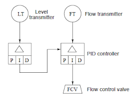
A cascaded control system, where the output of one
controller acts as the set-point for another controller to follow, appears in
functional diagram as shown below:
In the above cascaded control system, the primary
controller senses the level in a vessel, commanding the secondary (flow)
controller to maintain the necessary amount of flow either in or out of the
vessel as needed to maintain level at some point.
You can also read: How Loop Diagrams are used In Industrial Control
Functional diagrams may show varying degrees of
detail about the control strategies they document e.g. you may see the
auto/manual controls represented as separate entities in a functional diagram,
apart from the basic PID controller function. In the following Functional
Diagram, a transfer block (T) and two manual adjustment blocks (A) providing a
human operator with the ability to separately adjust the controller’s set point
and output (manipulated variables) and to transfer between automatic and manual
modes:
Rectangular blocks such as the Δ, P, I and D
shown in the diagram below represent automatic functions. Diamond-shaped
blocks such as A and T blocks represent manual functions which must be set by a
human operator. The Functional diagram also shows the presence of set point
tracking in the controller algorithm, a feature that forces the set point value
to equal the process variable value any time the controller is in manual mode.
A solid line in a functional diagram represent
analog (continuously variable) signals such as process variable, set point, and
manipulated variable. Dashed lines represent discrete (on/off) signal paths, in
this case the auto/manual state of the controller commanding the PID algorithms
to get its set point either from the operator’s input (A) or from the process
variable input (the flow transmitter: FT).
Don't miss out on key updates, join our newsletter list here.


No comments:
Post a Comment