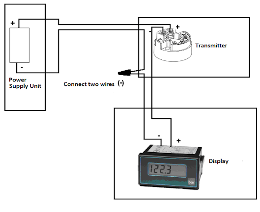
A 4-20 mA current loop is a series of connected elements
like flashlight batteries. The elements of a current loop are connected in
series. An easy way to remember the connections is (+) → (-), (-) → (+), then reverse the power supply connections (+) →(+), (-) →(-).
When we redraw the above circuit, we get to know
how to wire into a junction box as shown below:
To add a PLC or computer input, we just
insert into the loop. Always remember the (+) → (-), (-)→(+) except at the power supply.
Adding a computer or PLC input, the wiring will
look as follows:
Please note that you can only make one ground in a
4-20 mA system. Multiple grounds will cause erroneous readings.
You can also read: Key Elements that make up a Control Loop
Important items that must be checked
when determining loop compliance or Power supply voltage:
- The compliance voltage must be great enough to fully power all the loop devices at 20 mA. It is usually better to assume 25 mA max to allow yourself some ''head room''. You must also have enough voltage available to account for the drop in the wires.
- The loop power supply voltage must not exceed the maximum voltage rating of any device in the loop e.g. the transmitter above the maximum loop voltage of 30 VDC. Be aware of safety. If you are using low voltage wiring, you generally want to keep the voltage below 28 VDC.
- Note that, to calculate the required loop power supply (for compliance purpose), you add up the voltage drops around the loop at the highest expected current. Loop powered devices (like the transmitter and meter above), will tell you the required voltage in their data sheets.


No comments:
Post a Comment