We have different ways of measuring 4-20 mA loop current. Normally we use the standard milliammeter to measure the loop current but downside of this method, is you have to break the circuit, at some point to connect the meter in series with the current, which means interrupting the flow of information conveyed by that current. That why we have other methods you can use to measure the loop current without interrupting the process, you can use:
- Clamp-on milliammeter
- Test" diodes
- Shunt resistors
In this article we discuss the use of ''Test'' diodes to measure loop current in process measurement and control systems. The use of rectifying diode that is originally in
the loop circuit when it is commissioned to measure 4-20 mA loop signal ensures no interruption. A ”test”
diode may be placed anywhere in series within the loop in such a way that it
will be forward-biased. During normal operation, the diode will drop
approximately 0.7 volts, as it is typical for any silicon rectifying diode when
forward biased. To illustrate this, the following schematic diagram shows such
a diode installed in a 2-wire transmitter loop circuit:
 |
| Fig 1 |
If you connect a milliammeter in parallel with this
diode, (as shown in Fig 2), however, the very low input resistance of the ammeters, '' shorts past'' the diode and prevents any substantial voltage drop from forming across
it. Without the necessary forward voltage drop, the diode effectively
turns off and conducts 0 mA, leaving the entire loop current to pass through
the ammeter.
 |
| Fig 2 |
When you disconnect the milliammeter, the requisite
0.7 volt drop appears to turn on the diode, and all the loop current flows
through the diode again. From this, you can see there is no interruption
meaning that the technician may take current measurements this way with no
worries about generating false process variable indications, setting off alarms
or upsetting the process.
Such a diode may be installed at the nearest
junction box, between terminals on a terminal strip, or even incorporated into
the transmitter itself. If you check carefully, some process transmitters have
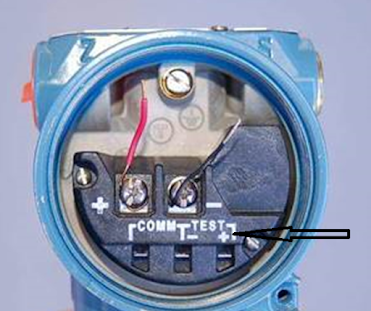
an extra pair of terminals labelled “Test” for this exact purpose. A diode is
already installed in the transmitter, and these “Test” terminals serve as
points to connect the milliameter across it. An example is shown of a Rosemount differential pressure transmitter:
 |
| Fig 3 |
Take note of the test points labelled “TEST” below
and to the right of the main screw terminals where the loop wiring attaches.
Connecting an ammeter to these two test points allows for direct measurement of
the 4-20 mA current signal without having to undo any wire connections in the
circuit.
Transmitters equipped with analog meter movements
for direct visual indication of the 4-20 mA signal usually connect the analog
milliameter in parallel with such a diode. The reason for doing this is to
maintain loop continuity in the event that the fine-wire coil inside the
milliameter movement were to accidentally break open.
Don't miss out on key updates, join our newsletter list here.
No comments:
Post a Comment