Showing posts with label Flowmeters. Show all posts

Sunday, May 21, 2023

Flowmeter Calibration Methods for Liquids

 The major principles employed for liquid flowmeter calibration are:

  • In-situ calibration methods {Insertion-point velocity and Dilution gauging/tracer technique}
  • Laboratory methods {master meter, volumetric gravimetric and pipe prover}

In-situ calibration methods

Insertion-point velocity – this is one of the simplest methods of in-situ flowmeter calibration. It utilizes point-velocity measuring devices where the calibration device selected is positioned in the flow stream adjacent to the flowmeter being calibrated, such that the mean flow velocity can be measured. In difficult situations a flow traverse can be carried out to establish the flow profile and mean flow velocity.

Dilution gauging/Tracer method – this method can be applied to closed-pipe and open-channel flowmeter calibration. An appropriate tracer (chemical or radioactive) is injected at an accurately measured constant rate and samples are taken from the flow stream at a point downstream of the injection point where complete mixing of the injected tracer will have taken place. By measuring the tracer concentration in the samples the tracer dilution can be determined and from this dilution and the injection rate the volumetric flow can be calculated.

Dilution gauging by tracer injection

                                    Figure 1.0 Dilution gauging by tracer injection

Alternatively a pulse of tracer material may be added to the flow stream and the time taken for the tracer to travel a known distance and reach a maximum concentration is a measure of the flow velocity.

Related: Instruments Errors and Calibration

Laboratory calibration methods

Master meter – for this method a meter of known accuracy is used as a calibration standard. The meter to be calibrated and the master meter are connected in series and are then subjected to the same flow regime. Note that, to ensure consistent accurate calibration the master meter itself must be subject to periodic calibration.

Volumetric method – in this technique, the flow of liquid through the meter being calibrated is diverted into a tank of known volume. When full, this known volume can be compared with integrated quantity registered by the flowmeter being calibrated.

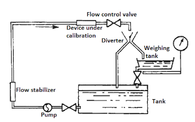
Gravimetric method – where the flow of liquid through the meter being calibrated is diverted into a vessel that can be weighed either continuously or after a predetermined time, the weight of the liquid is compared with the registered reading of the flowmeter being calibrated.
calibrating a flowmeter by weighing
Figure 1.1 calibrating a flowmeter by weighing


Pipe prover – this device also known as a meter prover, consists of a U-shaped length of pipe and a piston or elastic sphere. The flowmeter to be calibrated is installed on the inlet to the prover and the sphere is forced to travel to the length of the pipe by the flowing liquid. Switches are inserted near both ends of the pipe and operate when the spheres passes them. The swept volume of the pipe between the two switches is determined by initial calibration and this known volume is compared with that registered by the flowmeter during calibration.

Don't miss out on key updates, join our newsletter list here.

Wednesday, March 15, 2023

The Principle of Operation of an Electromagnetic Flowmeter

Electromagnetic flowmeters are widely used in industrial process flow measurement. These meters come with several features for example: they offer non-invasive flow measurement, they can measure reverse flows and are insensitive to viscosity, density and flow disturbances. Additionally, electromagnetic flowmeters can respond swiftly to flow changes and are linear devices for a wide range of measurements.

Working Principle of the Electromagnetic Flowmeter

Electromagnetic flowmeter operation is based on Faraday’s law of electromagnetic induction. The induced voltages in an electromagnetic flow meter are linearly proportional to the mean velocity of liquids or to the volumetric flow rates. As in the case in many applications, if the pipe walls are made from non-conducting elements, then the induced voltage is independent of the properties of the fluid.

Faraday’s law of induction states that if a conductor of length l (m) is moving with a velocity v (m/s) perpendicular to a magnetic field of flux density B (Tesla) then the induced voltage (e) across the ends of a conductor can be expressed by:

   e = Blv                                      

This is demonstrated in the figure below:

The operating principle of electromagnetic flowmeter
Figure 1.0 The Operational principle of electromagnetic flowmeter

In the above illustration, the magnetic field, the direction of the movement of the conductor, and the induced emf are all perpendicular to each other.

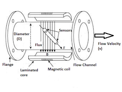
Let’s consider a simplified electromagnetic flowmeter construction below:

Construction of a practical electromagnetic flowmeter

Figure 1.1 Construction of practical electromagnetic flowmeter

The externally located electromagnets create a homogenous magnetic field (B) passing through the pipe and the liquid inside it. When a conducting flowing liquid cuts through the magnetic field, voltage is generated along the liquid path between the two electrodes positioned on the opposite sides of the pipe.

The conductor is the liquid flowing through the pipe, and the length of the conductor is the distance between the two electrodes, which is equal to the tube diameter (D). The velocity of the conductor is proportional to the mean flow velocity (v) of the liquid. Hence, the induced voltage becomes:

  e = BDv

If the magnetic field is constant and the diameter of the pipe is fixed, the magnitude of the induced voltage will be proportional to the velocity of the liquid. If the ends of the conductor, in this case the sensors that are connected to an external circuit, the induced voltage causes a current, i to flow, which can be processed appropriately as a measure of the flow rate.

Electromagnetic flowmeters are often calibrated to determine the volumetric flow of the liquid. The volume of liquid flow Q can be related to the average fluid velocity as:

Q = Av

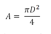
Where A is the area of the pipe, which can be written as:


Pipe Area

That gives the induced voltage as a function of the flow rate:

We know that fluid velocity v = Q/A

We can derive the induced voltage as:


Induced voltage in electromagnetic flowmeter

Equation 1.4 indicates that in a well-designed electromagnetic flowmeter, if all other parameters are kept constant, the induced voltage is linearly proportional to the liquid flow only.

Even though the induced voltage is directly proportional to the mean value of the liquid flow, the main problem in the use of electromagnetic flowmeters is that the amplitude of the induced voltage is small relative to extraneous voltages and noise. The noise sources include:

  • Capacitive coupling between signal and power circuits.
  • Stray voltage in the process liquid.
  • Capacitive coupling in connection leads.
  • Inductive coupling of the magnets within the flowmeter.
  • Electromechanical emf induced in the electrodes and the process fluid.

Key Merits of Electromagnetic Flowmeters

The electromagnetic flowmeters have the following advantages:

  • The output (voltage) is linearly proportional to the input (flow).
  • There is no obstacle to the flow path which may cause reduction in pressure.
  • The electromagnetic flowmeter can measure flow in pipes of any size provided a powerful magnetic field can be produced.
  • The output is not affected by changes in the characteristics of the liquid such as pressure, viscosity, and temperature.
You can also read: Working Principle of Ultrasonic Flowmeter

Shortcomings of Electromagnetic Flowmeters

The electromagnetic flowmeters have the following limitations:

  • The conductivity of the liquid being measured should not be less than 10 μꭥ/m.  It is important to note that most water based/aqueous solutions are adequately conductive while a majority of hydrocarbons solutions are not sufficiently conductive.
  • The operating cost is usually very high in an electromagnetic flowmeter specifically if heavy slurries are handled.
Related resource: Ultimate guide to Industrial flow Instruments

Don't miss out on key updates, join our newsletter list here.


Thursday, December 27, 2018

Key Applications of Thermal Mass Flowmeters

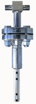
Thermal mass flowmeters work on the principle that when you place a heated object in the midst of a fluid flow stream and measure how much heat the fluid transfers away from the heated object, then you can be able to determine the mass flow rate. Industrial thermal mass flowmeters consists of a specially designed flow tube with two temperature sensors inside: One that is heated and one that is unheated. The heated sensor acts as the mass flow sensor (cooling down as flow rate increases) while the unheated sensor serves to compensate for the “ambient” temperature of the process fluid.  The following diagram shows an example of a thermal mass flowmeter from Magnetrol.
Magnetrol Thermal Flowmeter

An important factor in the calibration of a thermal mass flowmeter is the specific heat of the process fluid. Fluid with high specific heat values make good coolants because they are able to remove much heat energy from hot objects without experiencing great increases in temperature. Since thermal mass flowmeters work on the principle of convective cooling, this means a fluid having a high specific heat value will elicit a greater response from thermal mass flowmeter than exact same mass flow rate of a fluid having a lesser specific heat value. Therefore it is paramount that you know the specific heat value of the fluid you plan to measure with a thermal mass flowmeter and be assured that its specific heat value will remain constant. For this reason, thermal mass flowmeters are not suitable for measuring the flow rates of fluid streams whose chemical composition is likely to change over time.
Another potential limitation of thermal flowmeters is the sensitivity of some designs to changes in flow regime. Since the measurement principle is based on heat transfer by fluid convection, any factor influencing the convective heat-transfer efficiency will translate into a perceived difference in mass flow rate. Turbulent flows are more efficient at heat convection than laminar flows. Therefore, a change in flow regime from turbulent to laminar will cause a calibration shift for this design of thermal mass flowmeters.
So what are some of the applications where thermal flowmeters are used?
Generally thermal flowmeters are used in applications where the composition of the fluid is known especially in purified gases. Having said that, lets look at some of the areas where thermal flowmeters are commonly used:
Natural Gas
Flow measurement of natural gas fuel usage is important for combustion efficiency as well as general energy management projects for both industrial and commercial facilities. Thermal mass flowmeters will monitor the flow to individual combustion sources.
Air Efficiency
In combustion applications, thermal mass flow meters can ensure repeatability of air flow measurements to obtain an efficient air-to-fuel ratio. On compressed air, it is common to measure for plant allocation or to determine leaks.
Tank Blanketing
Nitrogen is frequently used to maintain an inert environment in the vapor space of a tank. Thermal meters are ideally suited for measuring the flow of nitrogen in such applications because they support mass measurement, they are easily installed into the pipe & are excellent at measuring low flow rates.
Flare & Vent Gas
Thermal mass meters are a particularly good fit for flare measurement. Flares can range from vent gases at atmospheric pressure to high flow applications needing extended turn down. Oil and Gas is a common industry here.
Follow this blog for updates on instrumentation articles or subscribe here.
Biogas
Both the landfills and anaerobic digesters at wastewater plants produce a mixture primarily composed of methane and carbon dioxide. Excellent low flow sensitivity, hot tap capabilities and mixed gas calibration make thermal mass flow measurement a popular technology.
Source: Magnetrol

Tuesday, November 6, 2018

How Pitot Tubes are used in Flow Measurement

Pitot tube sensors, orifice plates, flow nozzle or venturi tubes are classified as flow measuring devices which utilize differential pressure to measure volumetric flow. 

Pitot Tube Sensor

The Measuring Principle of Pitot Tube
The measuring principle of the pitot tube utilizes the differences between the pressure ridge on the upstream side of a bluff body and the static pressure on its down stream side.
Pitot Tube Measuring Principle

We have differences in pressures at S2 and S1. This difference in pressures is measured, then converted into fluid flow velocity, from this we can derive the volumetric flow using the continuity law with a pipe area A and an average flow velocity. i.e. Q=VA where Q is the volumetric flow, V is the average velocity and A is the pipe area.
Required fluid conditions 
To have good measurements from pitot tube sensors, we need to satisfy the following conditions:
  • The fluid has to completely fill the pipe so that the measured differential Pressure is representative of the volumetric flow. Fluids in partially filled pipes can only be measured if a full pipe can be arranged e.g. by means of siphon. 
  • The fluid must be single-phase. Two phase fluids e.g. water-air mixtures cannot be measured. 
  • The flow has to be sufficiently turbulent. Fluids of laminar nature cannot be measured with pitot tubes.
  • Fluid may contain small particles or bubbles. The pressure generated in front of the sensor apertures causes a deflection of the particles or bubbles. Fluids which tend to crystallize will quickly plug the pressure tubes of the sensor and therefore cannot be measured with pitot tubes. 
  • In steam measurement applications condensate pots are used inside of which a constant transition from steam to condensate and vice versa occurs. The pressure transfer is achieved via water columns. 

Industrial Applications of Pitot Tube Flowmeters
Pitot tube sensors are mainly used to measure the volumetric flow of liquids, gases and steam in closed pipes ranging from½“ to 480“ (DN 20 to DN 12000).
Examples of specific applications include: Precise volumetric flow measurement in batch processes, continuous measurement of liquid ingredients in the process industry, fuel, air, steam and gases as primary energy source as well as in control functions requiring a high degree of stability and repeatability.
Advantages of pitot tubes over orifice plates
  • They have a lower permanent pressure loss as compared to orifice plates. 
  • They have a shorter up/down straight pipe run requirements as compared to orifice plates. 
  • The profile of Pitot tube sensors is designed such that it is symmetrical to the plane between the pressure channels. This arrangement results in the same resistance values and thus the same k-factor with respect to the fluid properties during forward as well as reverse flow. The differential pressures generated by a given flow velocity are the same for flow in either direction. The only differ in the +/- sign. This constitutes an advantage of the orifice plate. Consider the figure below, of an orifice plate which because of its angled downstream corner has different resistances values for forward and reverse flows. It would indicate widely different pressures for the same flow velocity in opposite directions.
Orifice Plate Flow measurement


Some of the manufacturers of Pitot tube flow measurement Instruments, include:

Don't miss out on key updates, join our newsletter list here.

Monday, October 15, 2018

Variable Area Flowmeters


Variable area flowmeters typically feature a vertically positioned measuring cone through which the medium flows from bottom to top, lifting against the weight. We also have the horizontal and inverted (top to bottom) versions that are used where the installation structure doesn't allow for vertical version. 

We have two main types of variable area flowmeters:
  • Float type (Rotameter)
  • Tapered plug type
Float Type
The float is inside a tapered tube as shown below:

Variable Area Flowmeter

The fluid flows through the annular gap around the edge of the float. The friction causes a pressure drop over the float and the pressure forces the float upwards. Because the tube is tapered, the restriction is decreased as the float moves up. Eventually a level is reached where the restriction is just right to produce a pressure force that counteracts the weight of the float. The level of the float indicates the flow rate. If the flow changes, the float moves up or down to find a new balance position.

In case dangerous fluids are used, protection is needed against the tube fracturing. The tube may be made of non-magnetic metal. The float has a magnet on it, as it moves up and down; the magnet moves a follower and pointer on the outside. The position of the float may be measured electrically by building a movement transducer into the float.


Tapered Plug Type
This type has a tapered plug aligned inside a hole or orifice.

Variable Area Flowmeter

A spring holds it in place. The flow is restricted as it passes through the gap and a force is produced which moves the plug. Because it is tapered, the restriction changes and the plug takes a position where the pressure force just balances the spring force. The movement of the plug is transmitted with a magnet to an indicator on the outside.

Industrial Applications of Variable Area Flowmeters
Variable flowmeters are used in various industrial flow measurement applications, e.g.
  • Continuous gas and liquid measurement
  • Measurement of non-conductive media
  • Compressor monitoring
  • Industrial Burner controlling
  • Dry-run protection of pumps
Don't miss out on key updates, join our newsletter list here.

Sunday, September 23, 2018

Principle of Operation of Positive Displacement Flowmeters

Positive displacement flowmeters have a cyclic mechanism designed to pass a fixed volume of fluid through with every cycle.
Every cycle of the meter’s mechanism displaces a precisely defined (positive) quantity of fluid, so that a count of the number of mechanism cycles yields a precise quantity for the total fluid volume passed through the flowmeter.
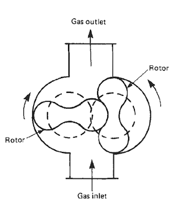
Example of Rotary Displacement flowmeter is shown below:

Rotary Displacement Meter


Each shaft revolution in a Rotary Displacement flowmeter represents a certain volume of fluid that has passed through the meter.
Besides, Rotary Displacement flowmeters, we have other types like Diaphragm meter (Bellows type), Liquid sealed drum (wet gas meter), Pistons etc.

Advantages of using Positive Displacement Flowmeters

Positive displacement flowmeters are immune to swirl and other large-scale fluid turbulence, and can be installed anywhere in a piping system. There is no need for long sections of straight of straight-length pipe upstream or downstream as with the case of Ultrasonic Flowmeters. Positive displacement flowmeters are also very linear, since the mechanism cycles are directly proportional to fluid volume.

Limitations of Positive Displacement Flowmeters

The sealing surfaces of rotating mechanisms are subject to wear and accumulating inaccuracies over time. The finely machined construction of a positive displacement flowmeter can suffer damage from abrasive materials like grit present in the fluid, meaning that these types of flowmeters are only used for clean fluid flow streams.


Applications of Positive Displacement Flowmeters
Positive displacement meters are commonly used for custody transfer of gas. Positive Displacement meters can measure high viscosity clean liquids as high as 1 Million centipoise, they also find application in water flow measurement.
Don't miss out on key updates, join our newsletter list here.

Saturday, September 22, 2018

The Working Principle of Ultrasonic Flowmeters

Ultrasonic Flowmeters measure the velocity of a flowing medium by monitoring the interaction between the flow stream and an ultrasonic sound wave transmitted through it.

The main techniques used are:
  •  Doppler
  • Time of flight/Transit-time
Doppler Flowmeters
These types of ultrasonic flowmeters use Doppler Effect which states that the frequency of sound changes if its source or reflector moves relative to the listener or monitor. The magnitude of the frequency change is an indication of the speed of the sound source or sound reflector.
Doppler flowmeter comprises a housing in which two piezoelectric crystals are potted, one being the transmitter and the other a receiver. This whole assembly is located on the pipe wall as shown below:

Principle of Operation of Doppler flowmeter

The transmitter transmits ultrasonic waves of frequency F1 at an angle ϴ to the flow stream. If the flow stream contains particles, entrained gas or other discontinuities, some of the transmitted energy will be reflected back to the receiver. If the fluid is travelling at a velocity V, the frequency of the reflected sound as monitored by the receiver can be shown to be F2 such that:
Principle of operation of doppler flowmeters-Equation

Where C is the velocity of sound in the fluid.
Rearranging the equation:

Principle of operation of doppler flowmeters equation

Which show velocity is proportional to the frequency change.

Applications of Doppler flowmeters

The Doppler flowmeter is normally used as an inexpensive clamp on flowmeter. The only operational constraints being that the flows stream must contain discontinuities of some kind, without which the device won’t work. Note the device cannot monitor clear liquids. For the Doppler flowmeter to work, the pipeline must be able to transmit acoustic signals.
Doppler flowmeter is mostly used as a flow switch or for flow indication where the absolute accuracy is not required.

Time of Flight Flowmeters

Ultrasonic flowmeters that use time of flight technique differ from Doppler flowmeters in that they rely on transmission of an ultrasonic pulse through the flow stream and therefore do not depend on the discontinuities or entrained particles in the flow stream for operation.
The principle of operation is based on the transmission of an ultrasonic sound wave between two points, first in the direction of flow, and then in the opposing flow. In each case the time of flight of the sound wave between the two points will have been modified by the velocity of the flowing medium and the difference between the flight times can be shown to be directly proportional to the flow velocity.
The sound waves are not generated in the direction of flow but at an angle across it as shown below:

Principle of operation of Time of flight ultrasonic flowmeters

Pulse transit times downstream T1 and upstream T2 along the path length D can be expressed as:
T1 = D/(C + V) and T2 = D/(C –V), where C is the velocity of sound in the fluid and V is the fluid velocity.
Now, T = T1 – T2 = 2DV/ (C2 V2)  (equation 1)
Since V2 is very small compared to C2 it can ignored. It is convenient to develop the expression in relation to frequency and remove the dependency on the velocity of sound C.
Since F1 = 1/T1   and F2 = 1/T2 and the average fluid velocity Vav = V/ (cosϴ)
Replacing T1 and T2   in equation 1 with respective Frequencies, we get:
F1  - F2  = (2Vav cosϴ)/D
The frequency difference is calculated by an electronic converter which gives an analog output proportional to average fluid velocity.
In practice, the piezoelectric ceramic transducers used act as both transmitters and receivers of the ultrasonic signals and thus only one is required on each side or the pipe.
Typically the flowmeter consists of a flow tube containing a pair of externally mounted transducers and a separate electronic converter/transmitter. Transducers may be wetted or non-wetted and consist of a piezoelectric crystal sized to give the desired frequency (typically 1 – 5 MHz for liquids and 0.2 -0.5 MHz for gases.

Advantages of ultrasonic Flowmeters

The unique advantage of ultrasonic flow measurement is the ability to measure flow through the use of temporary clamp-on sensors rather than a specialized flow tube with built in ultrasonic transducers.
Some modern ultrasonic flowmeters have the ability to switch back and forth between Doppler and transit-time (counter propagation) modes, automatically adapting to the fluid being sensed. This capability enhances the suitability of ultrasonic flowmeters to a wider range of process applications.

Limitations of Time of Flight Ultrasonic Flowmeters

Due to the fact that the flowmeter measures velocity across the center of the pipe, it is susceptible to flow profile effects and care should be taken to ensure there is sufficient length of straight pipe upstream or downstream of the flow tube to minimize this kind of effects.
To overcome this problem, manufacturers use multiple beam techniques where several chordal velocities are measured and the average computed, but note that, since ultrasonic flowmeters are easily affected by swirl and other large scale fluid disturbances, it is advisable to ensure an approximately 10 upstream and downstream diameters of straight pipe of the measurement flow tube, when installing them, this helps to stabilize the flow profile.
Also since this type of flowmeter relies on transmission through the flowing medium, fluids with a high solids or gas-bubble content cannot be measured well using ultrasonic meters.

Applications of Ultrasonic Flowmeters

Ultrasonic flowmeters are used in various industrial process measurement applications, and some of them include:
  • Measurement of both conductive and non-conductive liquids
  •  Measuring aqueous liquids as well as extreme viscous oils
  •  Measuring multiple products e.g. allocation measurements in on/off loading
  • The are used in all process industries: make up water, demineralized water, boiler feed water etc.
  • They are also considered for custody transfer natural gas

Don't miss out on key updates, join our newsletter list here.

Thursday, September 20, 2018

The Working Principle and Applications of Vortex Flowmeters

Vortex flowmeters are used to measure the flow of Gases, Vapours and liquids in completely filled pipes. The measuring principle behind vortex flowmeters is based on the Karman vortex street.
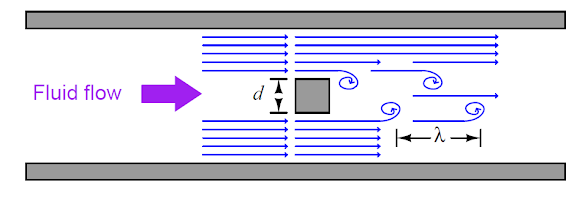
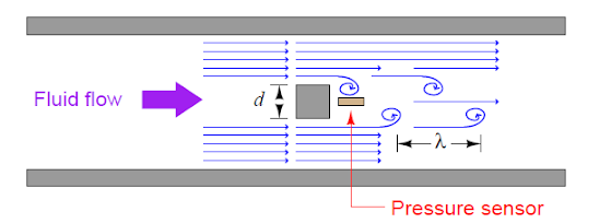
When a fluid moves with a high Reynolds number past a stationary object (a bluff body) there is tendency for the fluid to form vortices on either side of the object. Each vortex will form, then detach from the object and continue to move with the flowing gas or liquid, one side at a time in alternating fashion. This phenomenon is known as vortex shedding, and the pattern of moving vortices carried downstream of the stationary object is known as a vortex street.
From the research that was first done by Vincenc Strouhal then later on, by Theodore Von Karman, It was established that the distance between the successive vortices downstream of the stationary object is relatively constant, and directly proportional to the width of the object, for a wide range of Reynold number values.
The working Principle of Vortex Flowmeters

If consider these vortices as crests of a continuous wave, the distance between vortices may be represented by the symbol of wavelength ‘’lambda’’ (λ)


d- Object width
λ- Vortex street wavelength
S- Strouhal number
(λS = d) where S is approximately equal to 0.17
The wavelength (λ) is equivalent to d/0.17
If a differential Pressure sensor is installed immediately downstream of the stationary object in such an orientation that it detects the passing vortices as pressure variations, an alternating signal will be detected.
Working Principle of Vortex Flowmeters

The frequency of this alternating pressure signal is directly proportional to fluid velocity past the object, since the wavelength is constant.
Using the classic frequency velocity wavelength formula common to all travelling waves; λf = v, and since we know the wavelength from the above, we may substitute this into this formula.
Velocity (v) = wavelength (λ) x Frequency (f),
Velocity (v) = d/0.17 x f
Therefore, frequency (f) = 0.17v/d
Therefore the stationary object and pressure sensor installed in the middle of the pipe section constitute a flowmeter called a Vortex flowmeter; the output frequency of a vortex flowmeter is linearly proportional to volumetric flow rate.
The pressure sensors used in vortex flowmeters, are typically piezoelectric crystals.
The relationship between sensor frequency (f) and volumetric flow rate (Q) may be expressed as proportionality, with the letter k used to represent the constant of proportionality for any particular flowmeter:
Therefore, f = kQ
Where f = Frequency of output signal (Hz)
             Q =Volumetric flow rate (e.g. liters per second or gallons per second etc.)
             K = ‘’K’’ factor of the vortex shedding flow tube (e.g. pulses per gallon or pulses per a liter)
Each vortex flowmeter has a ‘’k’’ factor relating to the number of pulses generated per unit volume passed through the meter.
Counting the number of pulses over a certain time span yields total fluid volume passed through the meter over the same time span, making the vortex flowmeter readily adaptable for totalizing fluid volume.
The direct proportion between vortex frequency and volumetric flow rate means vortex flowmeters are linear-responding instruments.

Advantages of using Vortex Flowmeters
Vortex flowmeters have a wide turn down ratio or a wide range of flow measurement. They do not require signal characterization to function properly. Since they have no moving parts, they do not suffer the problems of wear and lubrication facing turbine or positive displacement meters and can measure erratic flows.

Disadvantages of using Vortex Flowmeters
The flowmeter may stop working below certain flow rate, known as low cut off. This is because, at low flow rates i.e. laminar flow (low Reynolds number values), fluid viscosity becomes sufficient to prevent vortices from forming, causing the vortex flowmeter to register zero flow even when there may be some flow in the pipe.

Industrial Applications of Vortex Flowmeters
Vortex flowmeters are used in measurement of saturated steam and super-heated steam. They are also used in measurement of consumption of industrial gases. You will find them commonly used in Steam boiler monitoring, measurement of consumption in compressed air systems, heat metering in steam & hot water and lastly in  SIP and CIP processes in the food, beverage and pharmaceutical industries among other areas not mentioned here. 

Don't miss out on key updates, join our newsletter list here.

Tuesday, September 18, 2018

The Working Principle of Coriolis Flowmeters

Critical process control applications require highly accurate measurement instruments. Coriolis flowmeters are one of the most accurate process measurement instruments and commonly applied in some of these applications.

Working of Coriolis Flowmeters
To help you understand the principle behind the Coriolis flowmeters, we will strive to make it as simple as possible.
Coriolis flowmeters works by shaking one or more tubes carrying the flowing fluid, then precisely measuring the frequency and phase of that shaking.
The back and forth shaking is driven by an electromagnetic coil, powered by an electronic amplifier circuit to shake the tube(s) at their mechanical resonant frequency.
Since this frequency depends on the mass of each tube, and the mass of the tubes depends on the density of the fluid filling the fixed volume of the tubes, the resonant frequency becomes an inverse indication of the fluid density whether or not the fluid is flowing through the tubes.

-Tube Frequency is inversely proportional to the Density

As the fluid begins to move through the tubes, the inertia of the moving fluid adds another dimension to the tube’s motion: the tubes begin to undulate i.e. twisting slightly instead of just shaking back and forth.
Coriolis Flowmeter working Principle

This twisting motion is directly proportional to the mass flow rate, and is internally measured by comparing the phase shift between motion at one point on the tube versus another point: the greater the undulation or twisting, the greater the phase shift between these two point’s vibrations.

-Tube twisting is directly proportional to Mass Flow rate

Temperature changes have the potential to interfere with density measurement that is why all Coriolis Flowmeters are equipped with RTD temperature sensors to continuously monitor the temperature of the vibrating tubes. The flowmeter’s microprocessor takes the tube’s temperature measurement and uses it to compensate for the resulting elasticity changes based on a prior modelling of the tube metal characteristics. This temperature measurement happens to be accessible as an auxiliary output signal, meaning that, Coriolis flowmeter may also work as a temperature transmitter in addition to measuring mass flow rate, and fluid density.
The ability of Coriolis flowmeter to measure three process variables i.e. Mass flow rate, Temperature and density makes it a very versatile instrument. This makes it easy to communicate in digital environment involving Foundation Fieldbus or Profibus Standard rather than the analog 4-20 mA signal. Fieldbus communication allows multiple variables to be transmitted by the device to the host system or on the same Fieldbus network.

The Advantages of Coriolis Flowmeters
Coriolis flowmeters are very accurate instruments, and reliable. They are completely immune to swirl and other fluid disturbances, hence they can easily be located anywhere in a piping system with no need for straight run pipe lengths upstream or downstream of the flowmeter. The ability of Coriolis flowmeter to measure true mass flow, along with their characteristic linearity and accuracy, makes them ideally suited for custody transfer applications, where the flow of fluid represents product being bought or sold.
The main disadvantage of Coriolis flowmeters is the high cost compared to other flowmeters especially for large pipe sizes. They have also more limited in operating temperature than other types of flowmeters and may have difficulty measuring low-density fluid -gases and mixed-phase i.e. liquid/vapor flows.  The bent tubes used to sense process flow may also trap process fluid inside to the point where it becomes unacceptable for hygienic applications e.g. Food Processing, Pharmaceuticals. That is why; we have new Coriolis tube design to try to overcome some of these problems. Straight-tube Coriolis flowmeters are slightly better than U-shaped tubes however U-shaped tubes aren’t as stiff as straight tubes, and so straight tube Coriolis flowmeters tend to be less sensitive to low flow rates than U-tube designs.