Showing posts with label Industrial Instrumentation. Show all posts

Wednesday, December 13, 2023

The Fundamentals of Semiconductor Junction Thermometers

Temperature sensors can be fabricated with semiconductor processing technology by employing the temperature characteristics of the pn junction.  The batch processing and well-defined manufacturing processes associated with semiconductor technology can provide low cost and consistent quality temperature sensors.

Most semiconductor junction temperature sensors utilize a diode-connected bipolar transistor (short-circuited collector-base junction). A constant current passed through the base-emitter junction produces a junction voltage between the base and emitter (Vbe) that is a linear function of the absolute temperature. The overall forward voltage drop has a temperature coefficient of approximately 2 mV °C-1.

Bipolar transistor configured as a temperature sensor

Fig: Bipolar transistor configured as a temperature sensor

In the above figure, the base of the transistor is shorted to the collector. A constant current flowing in the remaining pn (base to emitter) junction produces a forward voltage drop VF proportional to temperature.

The temperature coefficient of a semiconductor sensor is larger but still quite small when compared to a thermocouple or resistive temperature device/detector (RTD). Furthermore, the semiconductor sensor’s forward voltage has an offset that varies significantly from unit to unit. Nonetheless, the semiconductor junction voltage versus temperature is much more linear than that of a thermocouple or RTD. Also, the temperature-sensing element, circuitry is easily integrated to produce a monolithic temperature sensor with an output that can be easily interfaced to a microcontroller and to provide features that are useful in particular applications. For instance, by using an embedded temperature sensor with additional circuitry, protection features can be added to integrated circuits (ICs). A temperature sensor becomes an embedded item in a semiconductor product when it has a secondary or supplemental purpose instead of the primary function.

Sunday, May 21, 2023

Flowmeter Calibration Methods for Liquids

 The major principles employed for liquid flowmeter calibration are:

  • In-situ calibration methods {Insertion-point velocity and Dilution gauging/tracer technique}
  • Laboratory methods {master meter, volumetric gravimetric and pipe prover}

In-situ calibration methods

Insertion-point velocity – this is one of the simplest methods of in-situ flowmeter calibration. It utilizes point-velocity measuring devices where the calibration device selected is positioned in the flow stream adjacent to the flowmeter being calibrated, such that the mean flow velocity can be measured. In difficult situations a flow traverse can be carried out to establish the flow profile and mean flow velocity.

Dilution gauging/Tracer method – this method can be applied to closed-pipe and open-channel flowmeter calibration. An appropriate tracer (chemical or radioactive) is injected at an accurately measured constant rate and samples are taken from the flow stream at a point downstream of the injection point where complete mixing of the injected tracer will have taken place. By measuring the tracer concentration in the samples the tracer dilution can be determined and from this dilution and the injection rate the volumetric flow can be calculated.

Dilution gauging by tracer injection

                                    Figure 1.0 Dilution gauging by tracer injection

Alternatively a pulse of tracer material may be added to the flow stream and the time taken for the tracer to travel a known distance and reach a maximum concentration is a measure of the flow velocity.

Related: Instruments Errors and Calibration

Laboratory calibration methods

Master meter – for this method a meter of known accuracy is used as a calibration standard. The meter to be calibrated and the master meter are connected in series and are then subjected to the same flow regime. Note that, to ensure consistent accurate calibration the master meter itself must be subject to periodic calibration.

Volumetric method – in this technique, the flow of liquid through the meter being calibrated is diverted into a tank of known volume. When full, this known volume can be compared with integrated quantity registered by the flowmeter being calibrated.

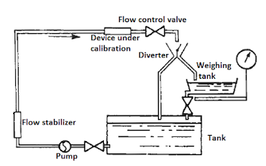
Gravimetric method – where the flow of liquid through the meter being calibrated is diverted into a vessel that can be weighed either continuously or after a predetermined time, the weight of the liquid is compared with the registered reading of the flowmeter being calibrated.

calibrating a flowmeter by weighing
Figure 1.1 calibrating a flowmeter by weighing


Pipe prover – this device also known as a meter prover, consists of a U-shaped length of pipe and a piston or elastic sphere. The flowmeter to be calibrated is installed on the inlet to the prover and the sphere is forced to travel to the length of the pipe by the flowing liquid. Switches are inserted near both ends of the pipe and operate when the spheres passes them. The swept volume of the pipe between the two switches is determined by initial calibration and this known volume is compared with that registered by the flowmeter during calibration.

Don't miss out on key updates, join our newsletter list here.

Wednesday, March 15, 2023

The Principle of Operation of an Electromagnetic Flowmeter

Electromagnetic flowmeters are widely used in industrial process flow measurement. These meters come with several features for example: they offer non-invasive flow measurement, they can measure reverse flows and are insensitive to viscosity, density and flow disturbances. Additionally, electromagnetic flowmeters can respond swiftly to flow changes and are linear devices for a wide range of measurements.

Working Principle of the Electromagnetic Flowmeter

Electromagnetic flowmeter operation is based on Faraday’s law of electromagnetic induction. The induced voltages in an electromagnetic flow meter are linearly proportional to the mean velocity of liquids or to the volumetric flow rates. As in the case in many applications, if the pipe walls are made from non-conducting elements, then the induced voltage is independent of the properties of the fluid.

Faraday’s law of induction states that if a conductor of length l (m) is moving with a velocity v (m/s) perpendicular to a magnetic field of flux density B (Tesla) then the induced voltage (e) across the ends of a conductor can be expressed by:

   e = Blv                                      

This is demonstrated in the figure below:

The operating principle of electromagnetic flowmeter
Figure 1.0 The Operational principle of electromagnetic flowmeter

In the above illustration, the magnetic field, the direction of the movement of the conductor, and the induced emf are all perpendicular to each other.

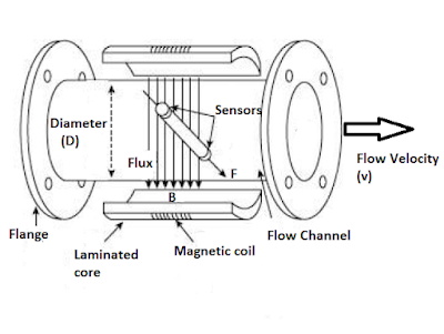
Let’s consider a simplified electromagnetic flowmeter construction below:

Construction of a practical electromagnetic flowmeter

Figure 1.1 Construction of practical electromagnetic flowmeter

The externally located electromagnets create a homogenous magnetic field (B) passing through the pipe and the liquid inside it. When a conducting flowing liquid cuts through the magnetic field, voltage is generated along the liquid path between the two electrodes positioned on the opposite sides of the pipe.

The conductor is the liquid flowing through the pipe, and the length of the conductor is the distance between the two electrodes, which is equal to the tube diameter (D). The velocity of the conductor is proportional to the mean flow velocity (v) of the liquid. Hence, the induced voltage becomes:

  e = BDv

If the magnetic field is constant and the diameter of the pipe is fixed, the magnitude of the induced voltage will be proportional to the velocity of the liquid. If the ends of the conductor, in this case the sensors that are connected to an external circuit, the induced voltage causes a current, i to flow, which can be processed appropriately as a measure of the flow rate.

Electromagnetic flowmeters are often calibrated to determine the volumetric flow of the liquid. The volume of liquid flow Q can be related to the average fluid velocity as:

Q = Av

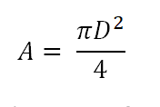
Where A is the area of the pipe, which can be written as:


Pipe Area

That gives the induced voltage as a function of the flow rate:

We know that fluid velocity v = Q/A

We can derive the induced voltage as:


Induced voltage in electromagnetic flowmeter

Equation 1.4 indicates that in a well-designed electromagnetic flowmeter, if all other parameters are kept constant, the induced voltage is linearly proportional to the liquid flow only.

Even though the induced voltage is directly proportional to the mean value of the liquid flow, the main problem in the use of electromagnetic flowmeters is that the amplitude of the induced voltage is small relative to extraneous voltages and noise. The noise sources include:

  • Capacitive coupling between signal and power circuits.
  • Stray voltage in the process liquid.
  • Capacitive coupling in connection leads.
  • Inductive coupling of the magnets within the flowmeter.
  • Electromechanical emf induced in the electrodes and the process fluid.

Key Merits of Electromagnetic Flowmeters

The electromagnetic flowmeters have the following advantages:

  • The output (voltage) is linearly proportional to the input (flow).
  • There is no obstacle to the flow path which may cause reduction in pressure.
  • The electromagnetic flowmeter can measure flow in pipes of any size provided a powerful magnetic field can be produced.
  • The output is not affected by changes in the characteristics of the liquid such as pressure, viscosity, and temperature.
You can also read: Working Principle of Ultrasonic Flowmeter

Shortcomings of Electromagnetic Flowmeters

The electromagnetic flowmeters have the following limitations:

  • The conductivity of the liquid being measured should not be less than 10 μꭥ/m.  It is important to note that most water based/aqueous solutions are adequately conductive while a majority of hydrocarbons solutions are not sufficiently conductive.
  • The operating cost is usually very high in an electromagnetic flowmeter specifically if heavy slurries are handled.
Related resource: Ultimate guide to Industrial flow Instruments

Don't miss out on key updates, join our newsletter list here.


Friday, May 3, 2019

Turning Fork Level Switches

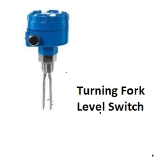
This level switch uses a metal tuning fork structure to detect the presence of a liquid or solid (powder or granules) in a vessel.
Turning Fork Level Switch
An electronic circuit continuously excites the tuning fork, causing it to mechanically vibrate. When the prongs of the fork contact anything with substantial mass, the resonant frequency of the structure dramatically decreases. The circuit detects this change and indicates the presence of material contacting the fork. The fork’s vibrating motion tends to shake off any accumulated material such that this style of level switch tends to be resistant to fouling.
You can also read: Ultrasonic Level Switches
Don't miss out on key updates, join our newsletter list here.
Tuesday, March 19, 2019

Types of Signal Converters Commonly used in Industrial Control


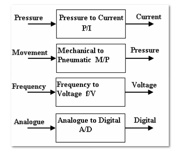
Signal converters change a signal from one form to another. In most cases, we have standard inputs and output ranges.
Types of signal converters

Most signal converters have two adjustments-zero and range.
Examples of Signal converters
Nozzle-flapper and differential pressure cells
The nozzle-flapper system is widely used in D.P. Cells. An example is shown below, that converts differential pressure (e.g. from a differential Pressure flow meter into a standard pneumatic signal). This is widely used in the control of air operated pipeline valves.
Flapper Nozzle System

The bellows respond to the differential pressure and moves the lever. This moves the flapper towards or a way from the nozzle. The air supply passes through a restrictor and leaks out of the nozzle. The output pressure hence depends on how close the flapper is to the end of the nozzle. The range of the instrument is adjusted by moving the pivot and zero position is adjusted by moving the relative position of the flapper and nozzle. This system is used in a variety of forms. Instead of bellows, a bourdon tube might be used and this is operated by an expansion type temperature sensor to produce a temperature-pneumatic signal converter.
Current/Pressure conversion 
The figures below show typical units for converting 4-20 mA into 0.2-1 bar or 3-15 psi. They contain adjustments for range and zero. They are widely used for converting the standard pneumatic and electric signals back and forth. They can also be adjusted to work with non standard inputs to convert them into a standard form.
Current to Pressure Converter (C/P)
Current to Pressure Converter

Pressure to Current Converter (P/C)
Pressure to Current Converter

Electric D.P. Cells
They provide the same functions as the pneumatic versions but they are given an output of 4-20 mA using electrical pressure transducers. They are typically used with D.P. Flow meters.
Differential Pressure Transmitter

Analogue -Digital Converters
Analogue to digital conversion is a process of turning an analogue voltage or current into a digital pattern which can read by a computer and processed, this is done by analogue -digital converters.  Lets look at the Binary Numbers, a number may be represented in digital form by simply setting a pattern of voltages on a line high or low. It is normal to use 4, 8, 16 or 32 lines. An 8 bit binary pattern is shown in the below figure:
Binary Numbers
The total pattern is called a word and the one above is an 8 bit word. The pattern may be stored in an 8 bit register. A register is a temporary store where the word may be manipulated. The Bit zero is called the least significant bit (LSB) and the bit with highest value is called the most significant bit (MSB). Each bit has a value of zero when off (LOW) or the value shown when on (HIGH). The maximum value for an 8 bit word is 255.
Digital to Analogue Converters
These are devices for converting a binary number into an analogue voltage. The change in the binary value from zero to a maximum corresponds with a change in the analogue value from 0 to maximum.
One of the manufacturers of signal converters is Omega.
Don't miss out on key updates, join our newsletter list here.

Sunday, March 10, 2019

The Inputs and Outputs of Process Measurement Instruments Commonly used in Control Systems

Basically when you are doing the troubleshooting of any instrumentation system you assume that every instrument has at least one input and at least one output and that the output(s) should accurately correspond to the input (s). In normal circumstances, if the instrument’s output is not corresponding to its input according to the instrument’s design function, then there could be something wrong with the instrument. Lets consider the inputs of the following examples of  instruments that are commonly used in process control systems:
  • Differential Pressure transmitter
  • Temperature Transmitter
  • Controller

Process measurement instruments


Controller
Each of the above instruments takes in (input) data and generates the (output) data.  In an instrumentation loop, the output of one instrument feeds into the input of the next. Such information is passed from one instrument to another.
By intercepting the data communicated between components of an instrument system, we are able to locate and isolate faults. For us to able to properly understand the intercepted data, we must understand the inputs and outputs of the respective instruments and the basic functions of those instruments. From the above diagrams, we  are able to highlight the kind of inputs and outputs for each of the instruments indicated.
To be able to check the right correspondence between the instrument inputs and outputs, we must therefore use appropriate test equipment to intercept the signals into and out of these instruments e. g. in case of analogue instruments using 4-20 mA signals we can use the electrical meters capable of measuring the current and voltage.
So what are some of the key considerations when using milliameters to measure loop current?
For you to measure the loop current, you have to break the circuit to connect the milliameter, in series with the current, and which means the current will fall to 0 mA until the meter is connected. Interrupting the current means interrupting the flow of information that is conveyed by that current, be it a process measurement or a command signal to a final control element. This can have adverse effects on the control system unless certain preparations are made before hand. The preparations can be in form of:
  • Informing the personal in charge that signal will be interrupted - state the number of times you intend to do the interruption.
  • For case, where the signal is coming from a process transmitter to a controller, the controller should be placed in manual mode, so that it will not cause an upset in the process. 
  • If the current drives process shutdown alarms, these should be disabled on temporarily basis, so that nothing shuts down upon the interruption of the signal.
  • All process alarms should be temporarily disables so that they do not cause panic.
  • If the current signal to be interrupted is a command signal from a controller to a final control element, the final control element either needs to be manually overridden so as to hold a fixed setting while the signal varies or it needs to be bypassed completely by some other devices (s)
Don't miss out on key updates, join our newsletter list here.


Thursday, December 27, 2018

Key Applications of Thermal Mass Flowmeters

Thermal mass flowmeters work on the principle that when you place a heated object in the midst of a fluid flow stream and measure how much heat the fluid transfers away from the heated object, then you can be able to determine the mass flow rate. Industrial thermal mass flowmeters consists of a specially designed flow tube with two temperature sensors inside: One that is heated and one that is unheated. The heated sensor acts as the mass flow sensor (cooling down as flow rate increases) while the unheated sensor serves to compensate for the “ambient” temperature of the process fluid.  The following diagram shows an example of a thermal mass flowmeter from Magnetrol.
Magnetrol Thermal Flowmeter

An important factor in the calibration of a thermal mass flowmeter is the specific heat of the process fluid. Fluid with high specific heat values make good coolants because they are able to remove much heat energy from hot objects without experiencing great increases in temperature. Since thermal mass flowmeters work on the principle of convective cooling, this means a fluid having a high specific heat value will elicit a greater response from thermal mass flowmeter than exact same mass flow rate of a fluid having a lesser specific heat value. Therefore it is paramount that you know the specific heat value of the fluid you plan to measure with a thermal mass flowmeter and be assured that its specific heat value will remain constant. For this reason, thermal mass flowmeters are not suitable for measuring the flow rates of fluid streams whose chemical composition is likely to change over time.
Another potential limitation of thermal flowmeters is the sensitivity of some designs to changes in flow regime. Since the measurement principle is based on heat transfer by fluid convection, any factor influencing the convective heat-transfer efficiency will translate into a perceived difference in mass flow rate. Turbulent flows are more efficient at heat convection than laminar flows. Therefore, a change in flow regime from turbulent to laminar will cause a calibration shift for this design of thermal mass flowmeters.
So what are some of the applications where thermal flowmeters are used?
Generally thermal flowmeters are used in applications where the composition of the fluid is known especially in purified gases. Having said that, lets look at some of the areas where thermal flowmeters are commonly used:
Natural Gas
Flow measurement of natural gas fuel usage is important for combustion efficiency as well as general energy management projects for both industrial and commercial facilities. Thermal mass flowmeters will monitor the flow to individual combustion sources.
Air Efficiency
In combustion applications, thermal mass flow meters can ensure repeatability of air flow measurements to obtain an efficient air-to-fuel ratio. On compressed air, it is common to measure for plant allocation or to determine leaks.
Tank Blanketing
Nitrogen is frequently used to maintain an inert environment in the vapor space of a tank. Thermal meters are ideally suited for measuring the flow of nitrogen in such applications because they support mass measurement, they are easily installed into the pipe & are excellent at measuring low flow rates.
Flare & Vent Gas
Thermal mass meters are a particularly good fit for flare measurement. Flares can range from vent gases at atmospheric pressure to high flow applications needing extended turn down. Oil and Gas is a common industry here.
Follow this blog for updates on instrumentation articles or subscribe here.
Biogas
Both the landfills and anaerobic digesters at wastewater plants produce a mixture primarily composed of methane and carbon dioxide. Excellent low flow sensitivity, hot tap capabilities and mixed gas calibration make thermal mass flow measurement a popular technology.
Source: Magnetrol

Thursday, December 13, 2018

Types of Proximity Sensors used in Industrial Control

Almost every automated manufacturing operation has sensors that ensure that the system is working correctly.
Examples of Sensors that are used in industrial control are:
Non-Contact Presence Sensors (Proximity Sensors)
Contact sensors are often avoided in automated systems because wherever parts touch there is wear and a potential for eventual failure of the sensor. Automated systems are increasingly being designed with non-contact sensors. The three most common types of non-contact sensors in use today are:
  • Inductive proximity sensor
  • Capacitive proximity sensor
  • Optical proximity sensor

The above sensors are actually transducers, but they include control circuitry that allows them to be used as switches. The circuitry changes an internal switch when the transducer output reaches a certain value.
Hall Effect Limit Switches
Hall Effect Limit Switch

The inductive Sensor
This is the most widely used non-contact sensor due to its small size, robustness, and low-cost. This type of sensor can only detect the presence of electrically conductive materials.
The DC power supplied is used to generate AC in an internal coil, which in turn causes an alternating magnetic field. If no conductive materials are near the face of the sensor, the only impedance to the internal AC is due to the inductance of the coil. If however, a conductive material enters the changing magnetic field, eddy currents are generated in that conductive material, and there is a resultant increase in the impedance to the AC in the proximity sensor. A current sensor, also built into the proximity sensor detects when there is a drop in the internal AC current due to increased impedance. The current controls a switch providing the output.

Inductive Sensor
Inductive Sensor

 
Capacitive proximity Sensors
These sensors sense the target objects due to the target’s ability to be electrically charged. This works both on conductors and non-conductors.
Inside the sensor is a circuit that uses the supplied DC power to generate AC, to measure the current in the internal AC circuit, and to switch the output circuit when the amount of AC current changes. Unlike the inductive sensor, the AC does not drive a coil, but instead tries to charge a capacitor. The AC can move current into and out of this plate only if there is another plate nearby that can hold the opposite charge. The target being sensed acts as the other plate.
Capacitive Proximity Sensor

If this object is near enough to the face of the capacitive sensor to be affected by the charge in the sensor’s internal capacitor plate, it will respond by becoming oppositely charged near the sensor, and the sensor will then be able to move significant into and out of its internal plate.
Optical Proximity Sensors
These are widely used in automated systems because they have been available longer and some can fit into small locations. They are commonly known as light beam sensors of the thru-beam type or of the retro-reflective type. A complete optical proximity sensor includes a light source, and a sensor that detects the light. The light source is supplied because it is usually critical that the light be tailored for the light sensor system. The light source generates a light of a particular frequency which is able to be detected by the light sensor in use. Infra-red light is used in most optical sensors. To make the light sensing system more foolproof, most optical proximity sensor light sources pulse the infra-red light on and off at a fixed frequency. The light sensor circuit is designed so that light that is not pulsing at this frequency is rejected.
Optical Sensors
Optical Proximity Sensors

The light sensor is a semiconductor device such as a photo diode which generates a small current when light energy strikes it or more commonly a photo transistor or a photodarlington that allows current to flow if light strikes it.
Some of the manufacturers of proximity sensors include:

Don't miss out on our updates, join our newsletter list here.
Wednesday, December 5, 2018

Key Considerations when Specifying Displacer Level Transmitters

Displacer level transmitter is used in Process measurements of liquids across many process industries. In this article we discuss the Principle of operation and industrial level applications that displacer transmitter technology offers.
Principle of Operation
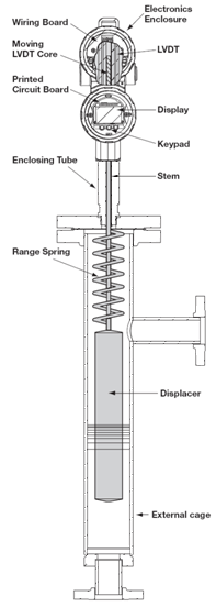
Displacer Level Transmitter

Operation is based on buoyancy force. The buoyancy force works on the displacer which will vertically move in (increasing liquid level) and out (decreasing liquid level) the linear differential transformer (LVDT). Due to this movement, voltages are induced in the secondary winding of the LVDT. These signals are then processed in the electronic circuitry and used to control the output signal.
Industrial Applications
Displacer transmitters are ideal solution for liquids or slurries, clean or dirty and light hydrocarbons to heavy acids with a specific gravity (SG) of 0.23 to 2.20.
Displacer transmitter technology works well in a variety of vessels including process & storage, bridles, bypass chambers, interfaces, sumps and pits up to unit pressure and temperature ratings. They can also handle most liquid conditions including varying dielectric, vapors, turbulence, foam, buildup, bubbling or boiling and high fill/empty rates.
Some of the specific industrial applications include:
Boiler control – The displacer unit provides a stable output signal for valve control on turbulent surface applications, such as feed water heaters, flash tanks, and reactors. 
Interface control on storage tanks – The displacers are tolerant of emulsions. They can track towards middle of emulsion, and are tolerant of unstable interface. They also ignore vapor/liquid interface point above displacer.
Mixing Tank – The displacer transmitter can also be used in harsh production environments like those in a mixing tank. It provides a stable output, easier to configure and is resistant to heavy surging caused by the mixer.
Water elevation – The displacer can be used to maintain a water elevation at a given height by sending out a proportional 3-15 PSIG signal (over a 14 ″ control band) to a control valve to maintain water level at midpoint by regulating the water flow rate out of the separator. The control valve is fully open at 15 PSIG input and fully closed at 3 PSIG input.
In Summary the advantages and limitations of Displacer transmitter include:
Advantages
  • Stable signal in turbulent applications
  • High Pressure/Temperature capabilities
  • No flexure of pressure boundary part

Limitations
  • Shifting SG can affect this technology

Some of the manufactures of Displacer level transmitters include:
Sources: Magnetrol
Don't miss out on our Instrumentation updates, join our newsletter list here