Showing posts with label Closed Loop Control System. Show all posts

Tuesday, October 9, 2018

Basics of a Control Loop

Control loop consists of all the key elements necessary to move the final control elements. We have different types of final control elements like the Valves, Motors, Fans etc. The final control elements makes it possible to keep controlled variable on target.

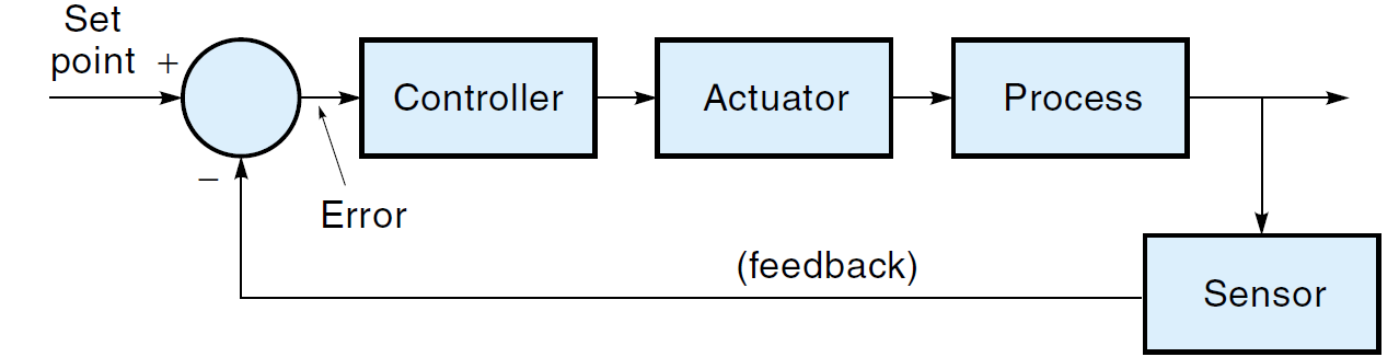
Let's Consider the following diagram:
Basics of a Control Loop

The Process measuring elements sends a signal to the controller. In this case the level transmitter sends the signal of the measured process variable to the level controller.  At the same time the already determined set point is compared with the signal coming from the measuring device. 
The error detector makes a comparison between the signal from the process and the set point signal. If there is a difference between this, an error signal is sent to the control logic that changes the position of final control device (In our case; it is the control valve). The change in the Final control device will cause a change in the process. This process will continue until the set point is maintained.
Key elements of a control loop includes:
  • The measuring device/Process measurement instrument
  • Controller
  • Final Control device, in this case, the control valve

Common terms used:
  • Process Variable
  • Manipulated Variable
  • Controller Error
  • Set point
Explaining the terms in more details:

Measuring device: This is the instrument that measures the physical quantity. This can be the temperature, level, flow rate, Pressure etc. It then converts this into a signal that can be easily picked up by the controller.
Process Variable: This is the process value or the process parameter i.e. the current measured value of a particular part of a process which is being monitored or controlled. The current level is the process variable while the desired level is known as the set point.
Process Control: The automatic control of certain process variables to hold them within given limits.
Set point: The reference value for a controlled variable in a process control loop.
Controller: The element in a process control loop that evaluates any error of the measured variable and initiates corrective action by changing the manipulated variable.
Controller Error: The difference in value between a measured signal and a set point.
Final Control Device (Actuator): A device that performs an action on one of the input variables of a process according to a signal received from the controller.
Manipulated Variable: The variable controlled by an actuator to correct for changes in the measured variable. 

Related:  The Transition from Relay Control Systems to PLC Systems

Don't miss out on key updates, join our newsletter list here.

Sunday, September 16, 2018

Stepper and Servo motors

Stepper and Servo motors find key applications in motion control.
Generally a motion control system consists of:
  • The mechanical part being moved
  • The motor (stepper or servo) with a feedback to provide an indication of actual position
  • Intelligent controller
  • The motion driver unit
  • Programming and operator interface software

Driving a controlled current through a number of coils within the motor generates the magnetic forces in a motor. Depending on their design, motors have many coils oriented in specific magnetic positions within their housing. By pulsing or steady control of current through different motor coils in a known pattern, electromagnetic fields develop in the motor, causing incremental or continuous motion.
The current and voltage that drives a motor typically comes from a power electronics device, known as an amplifier or power drive. Stepper and servo motors are located between the motion controller elements.

So what are stepper motors?
Stepper motors
are discrete motion devices that move to positions that relate directly to the number of input control pulses, at a velocity that relates directly to the pulse rate.
Stepper motors rely on the principle of commutation or alternating magnetic forces to provide predictable controlled motion.
Commutation in motion applications is the controlled sequencing of drive currents and voltages in motor coil winding to provide torque and therefore, movement.
In a stepper motor system, individual signals from a motion controller are converted into an energizing pattern for the motor.
As the commutation pattern varies, the motor moves from one discrete position to another.
Permanent Magnet stepper motor

When the pattern is held in a single state, the stepper motor holds its position with a known torque also called holding torque. These single-state locations are known as the full-step locations of a stepper motor. One key stepper motor specification is the number of full steps per revolution (rotary motion) or full steps per unit length (linear motion).
The steps/revolution parameter of a stepper motor indicates the basic resolution of the motor.
Let’s consider a stepper motor with a resolution of 200 steps/revolution, which can also be referred to as a 1.8 degree/step motor. If the motion controller outputs 200 steps to a full-step motor driver connected to a 1.8 degree stepper motor, the resulting movement would be a full 360° of the movement or one revolution of the motor. If those 200 steps were generated evenly over a period of one minute, the speed of rotation of the motor would be one revolution per minute (RPM).
Having looked at the stepper motors, let us now learn more about Servo motors.
Servomotors are continuous motion devices that use feedback signals to provide position and velocity control in a closed loop system.
The primary types of Servomotors are DC brush servo and brushless servo.
An open loop servomotor rotates or moves uncontrolled as long as the power is applied to it.
By implementing a control loop around a servomotor using a PID controller and feedback from an encoder device mounted on the motor, it is possible to accurately and reliably move to the desired position at well controlled velocities following your specified motion trajectory paths.
All servomotor systems use a motor driver pattern power unit to control the voltage and current that flows through the motor armature and motor winding.
The basic principle of motion in servo motors is based on the flow of current through wire coil, generating a magnetic field that reacts with permanent magnets in the motor to cause attraction and repelling forces that cause movement.

You can also read: Closed Loop Control System

DC brush servomotor
This is the simplest servomotor design. Actually it is cost effective for its performance and power in general servo applications.
DC brush servo motors are self-commutating motion devices that rotate continuously while current is applied to the motor brush contacts. The current flows through the brushes to the armature and then through the motor coils, creating the magnetic forces that cause motion. Changing the direction of the current flow through the motor reverses the direction of rotation.
Encoder feedback to the motion board is required to provide accurate control of position and velocity with a DC brush servomotor. Encoders are mounted on the shaft of a motor or on the coupled mechanical unit as a linear or rotary device, directly translating movement into feedback data.
Don't miss out on key updates, join our newsletter list here.

Thursday, September 13, 2018

Closed Loop Control System

Control systems are classified as either open loop or closed loop. In an open loop system, there is no feedback. In this case, the controller must independently determine the signal to be send to the final control element or the actuator. In this case, the controller can’t determine if the actuator correctly did what it was directed to do. The diagram below shows a representation of open loop control system:
Open Loop Control System

In a closed loop control system, also known as a feedback control system, the output of the process is constantly monitored by a sensor. The sensor samples the system output and passes this information back to the controller. The diagram below shows a representation of closed loop control system:

Because the controller knows what the system is actually doing, it can make any adjustments necessary to keep the output in the right place. This self-correcting feature of a closed loop control loop makes it preferred over open loop control in many applications.

The Controller is an analog or digital circuit that accepts data from the sensors then makes a decision before sending the appropriate commands to the final control element or the actuator. The controller works to keep the Controlled variable like the liquid level, position or velocity at a set point (SP). A closed control system or feedback control system accomplishes this by looking at the error (E) signal which is the difference between where the controlled variable is and where it is supposed to be. Based on the error signal, the controller decides the magnitude and the direction of the signal to the actuator.
Don't miss out on key updates, join our newsletter list here.

Key Elements that make up a Control Loop

A process is a sequence of events designed to control the flow of materials through a number of steps in a plant to produce a final product. To get a better understanding of a process control system, we can have a look at the following diagram showing elements in a continuous control process with a feedback loop.
Closed Loop Control System

Note that, the process can be a simple one, with a few steps, or a complex sequence of events with a large number of interrelated variables. The examples in the above diagram show single steps that may occur in a process.

Measurement is the determination of the physical amplitude of a parameter of a material. The measurement value must be consistent and repeatable.

Sensors are used for the measurement of the physical parameters. Sensors are devices that convert the physical parameters repeatedly and reliably into a form that can be used in the control system.  For example, you will find sensors being used to convert Pressure, Temperature, Flow, Level etc. into an electrical signal that is well understood by the system.

Error Detection is the determination of the difference between the amplitude of the measured variable and a desired set reference point or normally called set point. Any difference between the two is an error signal, which is amplified and conditioned to drive a control element. The reference point is usually stored in the memory of the controller.

The Controller is a microprocessor-based system that can determine the next step to be taken in a sequential process, or evaluate the error signal in a continuous process control system to determine what action is to be taken.

The controller can condition the signal, i.e. correct the signal for temperature effects or non-linearity in the sensor. The controller also has the parameters of the process input control element, and conditions the error sign to drive the final element.
The controller can monitor several input signals that are sometimes interrelated, and can drive several control elements simultaneously.

You can also read: 


The control element is the device that controls the incoming material to the process. Typically the element is a flow control element, and can have On/Off characteristics or can provide linear control with drive.  The control element is used to adjust the input to the process, bringing the output variable to the value of the set point.
In our figure above, the measuring element consists of a sensor to measure the physical property of a variable, a transducer to convert the sensor signal into an electrical signal, and a transmitter to amplify the electrical signal, so that it can be transmitted without loss.
The control element has an actuator which changes the electrical signal from the controller into a signal to operate the valve, and also control the valve. In a closed loop control system or a feedback loop, the controller has memory and a summing circuit to compare the set point to the sensed signal, so that it can generate an error signal.
The controller then uses the error signal to generate a correctional signal to control the valve via actuator and the input variable.

Don't miss out on key updates, join our newsletter list here.