Understanding the different components involved in
a given process control is important especially for its proper application, and
troubleshooting. In this article we look at the most common discrete components
used in industrial control applications.
 |
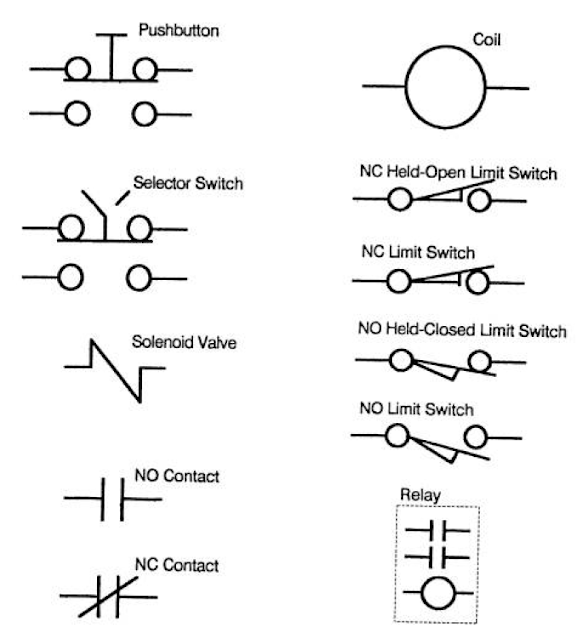
| COMMON ELECTRICAL SYMBOLS |
Contactors
Power consuming devices like Motors are usually
controlled by contactors having heavy duty contacts that can switch the power
circuits safely. The contactor will be actuated by an electromagnetic solenoid
(coil) which pulls the contacts closed when energized. They have an
arc-suppressing cover to quench the arc formed when the contacts open under
load. Note that AC contactors should never be used to break the current of a
loaded DC power circuit. It is more difficulty to quench the arc from a DC
power load because there is no AC ''zero crossing'' to interrupt the
current flow. DC contactors are designed to specifically handle DC current. You
will find they have embedded magnets, or special blow-out coils that are used
to stretch the arc long enough to break the DC current flow.
Devices using AC solenoids will have one or more
single turn coil (s), called a shading ring, embedded in the face of their
magnetic armature assembly. When the solenoid is energized, the magnetic field
has continuous reversals matching the alternating current that is been applied.
This will produce a noticeable hum or chatter because the magnetic structure is
not energized continuously. As the magnetic field reverses, it induces a current
in the shading ring, which in turn produces a secondary reversing magnetic
field. The secondary field is out of phase with that of the applied power, and
holds the armature faces sealed continuously between power reversals, and
minimizes the noise. Over time, shading rings tend to crack from the pounding
of the armature faces. When this happens, the solenoid will become very noisy,
coil current will increase, and premature failure will result. In an emergency,
one can remove the damaged ring and replace it temporarily with a shorted turn
of copper wire.
Solenoids
Solenoids are used to actuate brake/ clutch
mechanisms, hydraulic valves, air valves, steam valves or other devices that
require a push-pull button. Some solenoids can be quite large, requiring
contactors rated for their high current draw. Smaller pilot valves may draw no
more current than a simple relay. Some heavy duty units operate on DC current.
The DC solenoids are often specified for operation in dirty or corrosive areas
because current is controlled by circuit resistance, and will not rise if the
air-gap is fouled. AC solenoids depend upon the impedance of the circuit. If
the air-gap is not sealed properly, inductance reactance is reduced and coil
will draw excess current and over-heat. Shading rings must also be switched for
possible failures.
Relays
Relays have a similar construction to contactors,
but since they switch low-current logic signals, they do not have a requirement
for the heavy-duty contacts and arc-suppression hardware. Most relays contacts
have AC continuous ratings of no more than 10 A. They can close on an inrush
current of 150%, but only break 15% at 120 volts AC (vac). A NEMA A600 rating
limits the in-rush to 7200 volt-amperes (va), and a circuit breaking rating of
720 volt-amperes. As higher voltages are used, the current capacity goes down
proportionately. This difference in make and break ratings
closely matches the typical ratio of inrush and holding currents of AC control
coils. AC coils have relatively low resistance, allowing high in-rush currents.
As the coil is energized, the AC current builds up inductive reactance. Total
impedance (ohms), the vector sum of resistance and reactance, limits the
continuous holding current. The ratio of in-rush to holding current is often
5:1 or more. Maximum impedance is attained when the air gap in the magnetic
armature assembly has sealed closed. A failure to close this gap will reduce
the inductive reactance, allowing more current, which will overheat the coil,
causing premature coil failure. A shading ring fracture will
also lead to overheating and coil failure.
The same 10A contacts are only rated at 0.4 A DC,
at 125V, and 0.2 A DC at 250 V (50 va) because the small air-gaps are not
adequate to break a sustained DC arc. Voltages for DC logic controls seldom
exceed 24 volts with typical current in the milliamp ranges.
Relays may have multiple coils for latching and
unlatching of the contacts. Contacts may be normally open (NO), and or normally
closed (NC). The number of contacts usually varies from 1-8. Some relays use
contact cartridges which can be converted for either NO or NC operation. Most
standard relays will have totally isolated contacts. Some miniature relays have
type ”C” contacts where a NO and NC contact share a common terminal. This
construction requires careful planning to match the schematic wiring diagram to
actual relay construction.
Occasionally the required load on relay contacts
may be slightly higher than their normal rating. One can increase the current
capacity by connecting contacts in parallel, and improve the arc suppression by
connecting multiple contacts in series. When multiple contacts are used this
way, they should be on the same relay, because relay coils operating in
parallel may have a slight difference in their time-constant. If one
relay closes late, its contacts will take all the inrush punishment. If a
relay opens early, it will suffer more damage from breaking most of the full
load current.
Timers
Timers are a type of relay that have pneumatic or
electronic, time contacts to meet various sequencing requirements. They may be,
”stand-alone” relays or attachments to standard relays. On-delay timers actuate
the contacts at a preset time after the coil is energized, and reset instantly
with power off. Off-delay times actuate the contacts instantly when
energized, and reset a preset time after de-energizing. NO and/or NC contacts
may be time-closed or time-opened. Many timers also include instantaneous
contacts, actuated with no time delay. Instantaneous contacts may also be added
as a modification kit in some cases to stand-alone timers.
The coils of contactors and relay may be rated at a
different voltage than the circuits being switched. This provides isolation
between the low voltage logic circuits and higher voltages power circuits.
Push Buttons
Push-buttons may have a single contact block, or an
assembly of multiple contacts depending upon the complexity of the requirement.
Most push-buttons have a momentary change of state when depressed, then return
to normal when released. Some may have a push-pull actuator that latches in
each position. They are often used as a control-power master-switch with a
Pull-on/Push-off action.
Selector Switches
Many selector switches have the same construction
as push buttons, except that the contacts are actuated by rotating a handle or
key-switch. The rotating cam may be arranged with incremental indices so that
multiple positions and contact patterns can be used to select exclusive
operations. Contacts of push-buttons, selector switches, and limit switches
usually have the same rating as the logic relays 10A continuous at 120 (vac).
Limit Switches
Mechanical limit switches have many configurations.
Most will have both NO and NC contacts available. The contacts are switched
when the layer arm is rotated a few degrees by a moving cam or slider. The
conventional drawing will show the contact conditions when the machine is un-powered and at rest. It is assumed that the cam will normally strike the arm
on the switch to change the state of the contact(s).
Please don't miss out on Instrumentation & Automation updates, join our Newsletter list here.
Non-Contact Limit Switches
There are a number of electronic limit switches
that are used where it is not practicable to have an actuator arm physically
contact a product or machine part. The switches include: Photocells, and
Proximity switches (inductive, magnetic, and capacitive). In each case, a
control signal is activated whenever an object enters its operating field.
These devices require additional wiring to energize their power.


