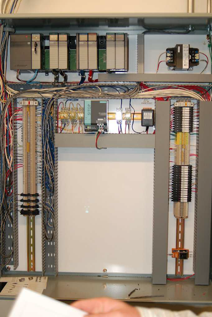
Programmable Logic Controllers (PLC) finds
common use in most industrial control applications. To be able to successful
integrate PLC into the control and management of your plant; you need to know its
features and capabilities.
You can also read:
The Bottom Line
PLC comes in
many sizes; meaning various I/O and program capacities. Their capabilities vary
greatly making generalizations difficult. The smallest sizes are typically referred
to as nano PLC, micro PLC and mini PLC having fixed inputs and outputs. The
mini PLC is used in small stand-alone applications.
The larger
PLCs support redundancy for CPU, power supply and possibly the control network,
but typically not for I/O cards although we have other large PLC that support
I/O redundancy by using duplicate I/O subsystems with separate backplanes where
the field instruments are wired in parallel to both I/O subsystems. The control
network is typically a standard industrial Ethernet application protocol over
Ethernet media and IP. For PLC the field cabling lands directly on the I/O
card.
PLC usually
supports very fast scan times as required in discrete manufacturing, especially
the discrete logic, however PID loops add to the CPU load much more than
discrete logic thus making the scan time slower. The scan time, although fast,
may vary with task loading. Loops are not handled individually in a PLC. Any
addition or change to the loop requires a download of the entire program which
affects other loops in the CPU.
The PLC
configuration software is separate from the HMI software as they generally come
from different manufacturer, meaning we have two separate databases. The logic
programming is first done in the PLC configuration software. Next the OPC
server has to be configured. Note, a OPC
server is a software program that converts the hardware communication
protocol used by a PLC into the OPC protocol and the OPC client software is any program that needs to connect to the
hardware such as Human Machine Interface (HMI). The OPC client uses the OPC
server to get data from or send commands to the hardware.
For a native
OPC server the configuration happens automatically but for a third-party OPC
server manual data mapping is required which is time consuming and error prone
requiring thorough testing hence native OPC server is preferred. Finally, the
HMI database has to be configured for graphics, alarms, trend etc.
If the HMI
software comes from the same manufacturer as the PLC, the intermediate data
mapping step may not be required, making the integration easier, however, even
if the PLC and HMI manufacturer are the same, the data mapping may still be
required in case the two products were designed separately.
You can also read:
- The Transition from Relays to PLCs Explained
- The Basics of Industrial Instrumentation and Control Systems
- Key Features of Distributed Control systems (DCS)
The Bottom Line
In most
cases, each PLC manufacturer has a native protocol, yet open standard, which
the PLC architecture is built around. It may be DeviceNet, Modbus, PROFIBUS, or
CC-link etc. The PLC comes with its own native interface cards for the native
protocol supported by the PLC manufacturer, but relies on third-party interface
cards for other fieldbus protocols. The engineering software therefore
automatically configures the communication interface card for the native
protocol, but for other field protocols the interface card must be configured
to map the variables before they can be used in the control strategy and
graphics.
Don't miss out on key updates, join our newsletter list here.

No comments:
Post a Comment