Tuesday, November 27, 2018

Key Components used in Industrial Control

Understanding the different components involved in a given process control is important especially for its proper application, and troubleshooting. In this article we look at the most common discrete components used in industrial control applications.
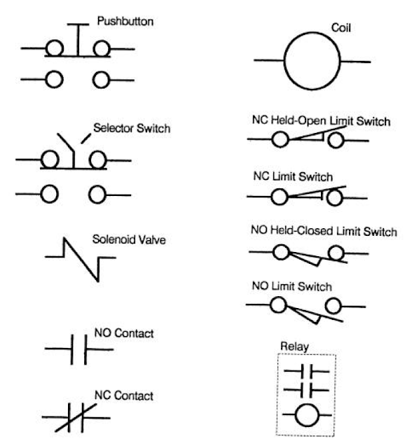
Electrical Symbols of Components commonly used in Industrial Control
COMMON ELECTRICAL SYMBOLS

Contactors
Power consuming devices like Motors are usually controlled by contactors having heavy duty contacts that can switch the power circuits safely. The contactor will be actuated by an electromagnetic solenoid (coil) which pulls the contacts closed when energized. They have an arc-suppressing cover to quench the arc formed when the contacts open under load. Note that AC contactors should never be used to break the current of a loaded DC power circuit. It is more difficulty to quench the arc from a DC power load because there is no AC  ''zero crossing'' to interrupt the current flow. DC contactors are designed to specifically handle DC current. You will find they have embedded magnets, or special blow-out coils that are used to stretch the arc long enough to break the DC current flow.
Devices using AC solenoids will have one or more single turn coil (s), called a shading ring, embedded in the face of their magnetic armature assembly. When the solenoid is energized, the magnetic field has continuous reversals matching the alternating current that is been applied. This will produce a noticeable hum or chatter because the magnetic structure is not energized continuously. As the magnetic field reverses, it induces a current in the shading ring, which in turn produces a secondary reversing magnetic field. The secondary field is out of phase with that of the applied power, and holds the armature faces sealed continuously between power reversals, and minimizes the noise. Over time, shading rings tend to crack from the pounding of the armature faces. When this happens, the solenoid will become very noisy, coil current will increase, and premature failure will result. In an emergency, one can remove the damaged ring and replace it temporarily with a shorted turn of copper wire.
Solenoids
Solenoids are used to actuate brake/ clutch mechanisms, hydraulic valves, air valves, steam valves or other devices that require a push-pull button. Some solenoids can be quite large, requiring contactors rated for their high current draw. Smaller pilot valves may draw no more current than a simple relay. Some heavy duty units operate on DC current. The DC solenoids are often specified for operation in dirty or corrosive areas because current is controlled by circuit resistance, and will not rise if the air-gap is fouled. AC solenoids depend upon the impedance of the circuit. If the air-gap is not sealed properly, inductance reactance is reduced and coil will draw excess current and over-heat. Shading rings must also be switched for possible failures.
Relays
Relays have a similar construction to contactors, but since they switch low-current logic signals, they do not have a requirement for the heavy-duty contacts and arc-suppression hardware. Most relays contacts have AC continuous ratings of no more than 10 A. They can close on an inrush current of 150%, but only break 15% at 120 volts AC (vac). A NEMA A600 rating limits the in-rush to 7200 volt-amperes (va), and a circuit breaking rating of 720 volt-amperes. As higher voltages are used, the current capacity goes down proportionately. This difference in make and break ratings closely matches the typical ratio of inrush and holding currents of AC control coils. AC coils have relatively low resistance, allowing high in-rush currents. As the coil is energized, the AC current builds up inductive reactance. Total impedance (ohms), the vector sum of resistance and reactance, limits the continuous holding current. The ratio of in-rush to holding current is often 5:1 or more. Maximum impedance is attained when the air gap in the magnetic armature assembly has sealed closed. A failure to close this gap will reduce the inductive reactance, allowing more current, which will overheat the coil, causing premature coil failure. A shading ring fracture will also lead to overheating and coil failure.
The same 10A contacts are only rated at 0.4 A DC, at 125V, and 0.2 A DC at 250 V (50 va) because the small air-gaps are not adequate to break a sustained DC arc. Voltages for DC logic controls seldom exceed 24 volts with typical current in the milliamp ranges.
Relays may have multiple coils for latching and unlatching of the contacts. Contacts may be normally open (NO), and or normally closed (NC). The number of contacts usually varies from 1-8. Some relays use contact cartridges which can be converted for either NO or NC operation. Most standard relays will have totally isolated contacts. Some miniature relays have type ”C” contacts where a NO and NC contact share a common terminal. This construction requires careful planning to match the schematic wiring diagram to actual relay construction.
Occasionally the required load on relay contacts may be slightly higher than their normal rating. One can increase the current capacity by connecting contacts in parallel, and improve the arc suppression by connecting multiple contacts in series. When multiple contacts are used this way, they should be on the same relay, because relay coils operating in parallel may have a slight difference in their time-constant.  If one relay closes late, its contacts will take all the inrush punishment. If a relay opens early, it will suffer more damage from breaking most of the full load current.
Timers
Timers are a type of relay that have pneumatic or electronic, time contacts to meet various sequencing requirements. They may be, ”stand-alone” relays or attachments to standard relays. On-delay timers actuate the contacts at a preset time after the coil is energized, and reset instantly with power off.  Off-delay times actuate the contacts instantly when energized, and reset a preset time after de-energizing. NO and/or NC contacts may be time-closed or time-opened. Many timers also include instantaneous contacts, actuated with no time delay. Instantaneous contacts may also be added as a modification kit in some cases to stand-alone timers.
The coils of contactors and relay may be rated at a different voltage than the circuits being switched. This provides isolation between the low voltage logic circuits and higher voltages power circuits.
Push Buttons
Push-buttons may have a single contact block, or an assembly of multiple contacts depending upon the complexity of the requirement. Most push-buttons have a momentary change of state when depressed, then return to normal when released. Some may have a push-pull actuator that latches in each position. They are often used as a control-power master-switch with a Pull-on/Push-off action.
Selector Switches
Many selector switches have the same construction as push buttons, except that the contacts are actuated by rotating a handle or key-switch. The rotating cam may be arranged with incremental indices so that multiple positions and contact patterns can be used to select exclusive operations. Contacts of push-buttons, selector switches, and limit switches usually have the same rating as the logic relays 10A continuous at 120 (vac).
Limit Switches
Mechanical limit switches have many configurations. Most will have both NO and NC contacts available. The contacts are switched when the layer arm is rotated a few degrees by a moving cam or slider. The conventional drawing will show the contact conditions when the machine is un-powered and at rest. It is assumed that the cam will normally strike the arm on the switch to change the state of the contact(s).
Please don't miss out on Instrumentation & Automation updates, join our Newsletter list here.
Non-Contact Limit Switches
There are a number of electronic limit switches that are used where it is not practicable to have an actuator arm physically contact a product or machine part. The switches include: Photocells, and Proximity switches (inductive, magnetic, and capacitive). In each case, a control signal is activated whenever an object enters its operating field. These devices require additional wiring to energize their power.
Saturday, November 24, 2018

The Basics of a Process Control System

Instrumentation is a science that deals with measurements and control of processes. Instrumentation is applied in almost any field from Medical, Manufacturing of pharmaceutical drugs, to simple processes like temperature control in homes using Thermostats. Note that if we can’t measure it then we have no need of controlling it.
Measurements can be in form of Fluid pressure, Fluid volume, Fluid Flow rate, Temperature, Electrical voltage or current, Chemical concentration etc. Once we have the quantity of the measured value,  we then transmit a signal  representing this quantity to an indicating or computing device where either human or automated action then takes place. If the controlling action is automated, the computer sends a signal to a final controlling device which then influences the quantity being measured. The final control device can be in the form of:
  • Electric motor
  • Control valve-for throttling the flow rate of a fluid
  • Electric heater
The measurement device and the final control device connect to some physical system called the process.
 
Process Control Basics
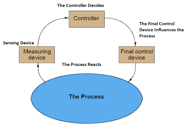
Block Diagram of a Process Control System

  • The measuring device senses
  • The Controller decides
  • The final control device influences the process
  • The process reacts to the influence of the final control

You can also read: Basics of a Control Loop
So in a nutshell this is what we call a Process control system.
Don't miss out on key updates, join our newsletter list here.

Friday, November 23, 2018

Key differences between PLC and DCS systems

We have so many people with questions as to what are the similarities and differences if any between PLC and DCS systems. We will try to describe the working of these two systems and in the process help you understand the functions of each system.
Initially DCS was focused only on process control with analog signals that were used as main control system in process industries like Refining, Chemicals, and Petrochemicals etc. while PLC was focused on discrete automation with discrete on-off signals, that were used for example in Factory assembly lines and bottle lines but today DCS supports discrete I/O and some logic functions and PLCs support analog I/O with some control functions. In some instances Both PLC and DCS are used in the same plant i.e. PLCs are used on separate units on a plant floor which are then integrated with main plant-wide DCS for Control and Monitoring.
Let us now look at each system separately to help us understand more how they work.
PLC
Programmable Logic Controllers (PLCs) comes in different sizes which means various I/O and program capacities. Smallest sized PLCs are typically referred to as nano PLCs, micro PLCs and mini PLCs. They have fixed I/O and mainly used in stand-alone applications.
Large PLC support redundancy for CPU, power supply and possibly the control network, but typically not for I/O cards though there are large PLCs that support I/O redundancy by using duplicate I/O-subsystems with separate backplanes where the field instruments are wired in parallel to both I/O subsystems. The control network is typically a standard industrial Ethernet application protocol over Ethernet media and IP. The Field cabling comes directly onto the I/O card.
PLC usually support very fast scan times as required in discrete manufacturing but PID loops add to the CPU load, much more than discrete load thus making the scan time slower.
Loops are not handled individually in a PLC. Addition or change to loop requires a download of the entire program which affects other loops in the CPU as well.
PLCs are built around a given native protocol, this maybe: PROFIBUS, Modbus, DeviceNet etc. The PLC comes with its own native interface cards for native protocol supported by the PLC maker but relies on third-party interface cards for other Fieldbus protocols. The engineering software therefore automatically configures the communication interface card for the native protocol.
Key Points to note on PLC
PLCs were designed to eliminate assembly-line relays during model changeovers. PLC is easier to change than relay panels; this has reduced the installation and operational cost of the control system compared with electromechanical relay systems.

A basic block diagram of PLC system
BLOCK DIAGRAM OF A PLC SYSTEM

PLC offers the following advantages:
  • Ease of programming and reprogramming in the plant
  • Programming language is based on relay wiring symbols familiar to most plant electrical and instrumentation personnel
  • High Reliability and minimal maintenance
  • Small physical size
  • Ability to communicate with computer systems in the plant
  • Moderate to low initial investment cost
  • Available in modular designs
DCS
Distributed Control System (DCS) supports redundancy for controllers, power supply and control network as well as redundant I/O cards including fieldbus interface cards in the same backplane. The control network supports peer-to-peer communication between controllers. The control network is typically a proprietary application protocol over Ethernet media and IP. The field cabling in DCS lands on a Field Terminal Assembly (FTA) where a special system cable with a connector takes the signals to the I/O card.
Loops in a DCS are executed individually. The scan time in a DCS is set individually for each loop. Most loops run at 1000ms although 250ms is common for pressure and flow loops in refining and petrochemicals and even 100ms is also possible. The scan time is constant, and does not change with task loading. This is important for PID control and time-based functions such as integration/totalizing and lead-lag dynamic compensation.
Loops in a DCS are managed individually. A change and download to one loop doesn’t affect the other loops.
A DCS has an integrated development environment where I/O control strategy and operator graphics are created together and stored in a single database. This means once a tag is created in the DCS it automatically becomes available everywhere in the system with the same human readable tag name for use in basic control, advanced control, graphics, faceplates, trending, alarming, and turning etc.  Without mapping data through registers or other tag names makes it easy to do changes or additions.
The Sensor & Actuator level “H1” Fieldbus network supported by DCS is basically FOUNDATION fieldbus for instrumentation and PROFIBUS-DP for motor controls.
The DCS comes with its own native Fieldbus interface cards. The engineering software therefore automatically configures the communication interface cards for the variables used in the control strategy and graphics.
Key Points to Note on DCS
DCS is miniaturized version of the multitasking, multivariable, multi-loop controller used for process control. It is functionally and geographically processing distributed system. Equipment making up a DCS is separated by function and is installed in two different work areas of a processing installation. Equipment for operator to monitor process condition and to manipulate the set point of the process operation is located in a central control room; from where the operator can view information transmitted from the process area and displayed on a video display unit and can change control condition from a keyboard. DCS systems are suitable for the following processes:

  • Where a single centralized system is not adequate i.e. Power, Steel, Pulp & Paper plants, Fertilizer etc.
  • Processes of different level of hierarchy
  • Processes which can be divided into different and functionally independent sections, based on functional scope and geographical distribution
DCS offers the following Advantages:
  • Compact to contain ON/OFF controllers
  • Reduced complexity and easy expandability
  • High Speed of the control processing
  • Control Algorithms changes do not call for hardware changes
  • Continuous trend data is available
  • User friendly but higher data security
  • Plant data are transparent on the network
  • Sequential, batching and feedback control are possible
Don't miss out on key updates, join our newsletter list here.
Differences between PLC and DCS based Systems
                PLC
           DCS
Redundancy not possible or limited
Redundancy possible at every level
It is used for low loop count
It is used for any loop count
Performance drops with increasing loop count
No change in performance with increasing loop count
Purely free running mode
Highly efficient multitasking mode
Analog processing simulated through digital computer
Analog processing done in real frequency domain function
No interplant connectivity
Fully Functional Inter-plant connectivity
Individual database for every node
System-wide global database
Typical performance: 100 PID loops/sec
Typical Performance: More than 1000 PID loops/sec.

Do you have comments or questions on PLC or DCS? Feel free to post them in the comments section below. 


Monday, November 19, 2018

Components in a Controlled Automation System

Essential components in any controlled automation system include:
  • The actuator (which does the work)
  • The controller (which ”tells” the actuator to do the work)
  • The sensor (which provides the feedback to the controller so that it knows the actuator is doing work)

An example of a simple controlled automation system is shown below:
Controlled Automation System

A controlled system may either be analog controlled system or digital controlled system. Let's consider the following analog controlled system:
Controlled Automation System

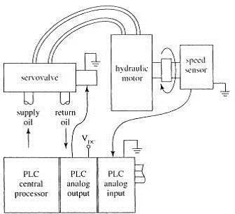
The actuator is a hydraulic servovalve and a fluid motor. The servovalve opens proportionally with the voltage it receives from the controller and the fluid motor rotates faster if it receives more hydraulic fluid. There is a speed sensor connected to the motor shaft, which outputs a voltage signal proportional to the shaft speed. The controller is programmed to move the output shaft at a given speed until a load is at given position. When the program requires the move to take place, the controller outputs an approximately correct voltage to the servovalve, then monitors the sensor’s feedback signal. If the speed sensor’s output is different from expected i.e. indicating wrong motor speed, the controller increases or decreases the voltage supplied to the servovalve until the correct feedback is achieved. The motor speed is controlled until the move finishes. As with any other control system, the program may include a function to notify a human operator if speed control isn’t working.
Having looked at analog controlled system above, let's now consider an example of a digital controlled system:
Controlled Automation System

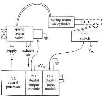
The above figure represents a simple digital controlled system in which the actuator consists of a pneumatic valve and a pneumatic cylinder that must be either fully extended or retracted. The controller is a PLC that has been programmed to extend the cylinder during some more complicated process and to go on to the next step in the process only after the cylinder extends. When it is time to extend the cylinder, the PLC supplies voltage to the valve, which should open to provide air to the cylinder, which then extend. If all goes well, after a short time the PLC will receive a change in voltage level from the limit switch, allowing it to execute the next step in the process. If the voltage from the switch does not change for any reason ( faulty valve or cylinder or switch, break in a wire, obstruction preventing full cylinder extension etc.), the PLC will not execute the next step. The PLC may even be programmed to turn on a “fault” light when such a delay occurs.

Don't miss out on our Industrial Instrumentation & Automation updates, join our Newsletter list here.

Sunday, November 18, 2018

Key Features and Applications of Remote Terminal Units (RTU)

Remote Terminal Units also called Remote Telemetry Units or Remote Telecontrol Units are Microprocessor controlled devices that interfaces in the physical world to either SCADA (Supervisory Control and Data acquisition) system or DCS (Distributed and Control system).  They transmit data to a master system and uses messages from the master supervisory system to control objects connected to the system.
They are designed for use in applications in remote locations unattended. These locations may have limited to no power, hence RTUs are designed to consume low power than DCS and PLC & this enables operation on solar power and batteries.
In application where supervision is done from distant central location, the SCADA software sits in the central office connected over a backhaul network typically using radio communication to the RTUs located far away and in most cases geographically spread out. The communication may be interrupted for long periods of time therefore RTUs have on-board  data storage continuing local data collection for more than a month if backhaul communication is lost as well as “history backfill’’ uploading this data once the connection is established again. Report by exception communication mechanisms are often used to minimize backhaul communication using Wide Area Networks e.g. Mobile, Microwave, Satellite.
RTU in Multidrop Communication System

Remote Terminal Units (RTU) Configuration
The RTU configuration software is separate from the HMI (Human Machine Interface) software from a third-party manufacturer i.e. two separate databases. RTU is configured first; next the OPC server is configured. For a native OPC server this happens automatically, but for OPC server from a third-party, manual data mapping is required which can be time-consuming and error prone requiring thorough testing. In most cases native OPC server is preferred. To finalize, the HMI database has to be configured for graphics, alarms, and trends etc.
The 4-20 mA AI and AO cards for a RTU optionally support native HART pass through hence separate HART multiplexer (MUX) hardware and associated work is not required. Native HART pass through AI and AO cards are much easier to integrate and should be specified if 4-20 mA is used. Since RTUs are generally used in very slow monitoring applications that don’t require fast control, some applications do not use the real-time analog 4-20 mA but only the digital HART communication multi-drop topology. This means the field instruments draw less than 4 mA instead of up to 20 mA hence further reducing the overall power consumption.
Applications of Remote Terminal Units (RTU)
Remote terminal units are commonly used in the following applications:
  • Electrical Power Transmission Networks and Associated Equipment.
  • Remote Monitoring of Functions and the whole Instrumentation Network in Oil and Gas (offshore platforms, onshore oil wells, Pump Stations on Pipelines)
  • Water and Wastewater collection and supply networks including the Pumping stations.
Don't miss our on our Industrial Instrumentation updates, join our Newsletter list here.

How Triacs are used in Industrial Control Applications


The Triac is a three-terminal device that is similar to the SCR except that the Triacs can conduct current in both directions. Its primary use is to control power to AC loads such as turning AC motors on and off or varying the power for lighting and heating systems. The Triac is a solid state device that acts like two SCRs that have been connected in parallel with each other (inversely) so that one SCR will conduct the positive half-cycle and the other will conduct the negative half-cycle. Before the triac was designed as a single component, two SCRs were actually used for this purpose.
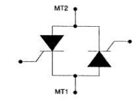
The figure 1 below shows the symbol for the triac, and its pn Structure. The terminals of the triac are identified as main terminal 1 (MT1), main terminal 2 (MT2), and gate. The multiple pn structure is actually a combination of two four-layer (pnpn) junctions.


Triacs
Figure 1

As the name suggests, the load current passes through the main terminals, and the gate controls the flow. Figure 2 below shows the equivalent circuit of the triac, which consists of two back-to-back SCRs with a common gate.
Triacs
Figure 2
Operation of the Triac
The operation of the triac can be explained by the two-SCR model in Figure 2.  From the figure, you can see the SCRs are connected in an inverse parallel configuration. One of the SCRs will conduct positive voltage and the other will conduct negative voltage.
When MT2 is more positive, the current flows through first SCR; when MT1 is more positive the current flows through Second SCR.
Unlike the two SCRs, the Triac is triggered by a single gate. This prevents problems of one SCR not firing at the correct time and overloading the other.
The operating characteristics of the Triac are best explained using the characteristic curve shown in Figure 3:


Triacs
Figure 3
In the figure above, you can see that the triac can conduct both positive and negative current. The Voltage is shown along the horizontal x-axis, and current is shown along the vertical y-axis. This diagram also shows a second graph with four quadrants. These quadrants are used to explain the operation of the triac as polarity to its MT1 and MT2 and gate changes.
Notice that the right half of the graph (in quadrant 1) looks just like the SCR curve; no current flows until either the break over voltage is reached or the gate is triggered (indicated by dashed line).
This same pattern is repeated in quadrant 3 (for voltage and current of the opposite direction). Also, like the SCR, once the triac is triggered on, it will remain on by itself until the load current drops below the holding current value (IH)
A Single cycle of AC has a positive and a negative half-cycle. The triac requires a trigger pulse at the gate for each half-cycle and works best if the trigger is positive for the positive half-cycle and negative for the negative half-circle (Although in most cases the triac will also trigger if the gate goes negative in the positive half-cycle and if it goes positive in the negative half-cycle.
Applications of Triacs
The Triac is required in circuits where AC Voltage and Current need to be controlled like the SCR controls dc current. Another difference between the triac and SCR is that the Triac can be turned on either by a positive or negative gate pulse. The gate pulse need only be momentary and the Triac will remain in conduction until the conditions for commutation are satisfied.
A triac can be used as an-off solid-state switch for AC loads or to regulate power to an AC load, such as dimmer switch.
Triacs are available in various packages, some of which can handle currents up to 50 A (which is considerably less than the SCR).
Don't miss out on key updates, join our newsletter list here.

How Silicon Controlled Rectifiers (SCRs) are used in Industrial Control


Brief Background on Industrial Electronics
Silicon Controlled Rectifiers (SCRs), Triacs and other high –powered transistors are used in many types of circuits to control large voltages and currents. Many of these use 480 VAC 3 Phase circuits and can control over 50 A. These devices offer control circuits for general purpose power supplies, AC and DC Variable speed motor drives, Servo motor controls, Stepper motor controls, high frequency power supplies, welding power supplies etc. SCRs, Triacs, and any other solid-state devices used for switching larger voltages and currents on and off are commonly called thyristors. Thyristors control switching in an on-off manner similar to a light switch which is different from a transistor that can vary the amount in its emitter-collector circuit by changing the bias on its base. The amount of current that flows through a thyristor must be controlled by adjusting the point in a sine wave where the device is turned on.
Silicon Controlled Rectifiers (SCRs)
The figure 1 below shows a symbol for the SCR and identifies the anode, cathode, and gate terminals. The cathode is identified by the letter C or K. The diagram also shows several types of SCRs.
Silicon Controlled Rectifiers
Figure 1
How Silicon Controlled Rectifiers Work
The SCR acts like a solid-state switch in that the current will pass through its anode-cathode circuit to a load if a signal is received at its gate. The SCR is different from a traditional switch in that the SCR will change ac voltage to dc voltage (rectify) if ac voltage is used as the power supply. The SCR is also different from a traditional switch in that the amount of time the SCR conducts can be varied so that the amount of current provided to the load will be varied from near zero to maximum of the power supply.


Silicon Controlled Rectifiers
Figure 2
The SCR can vary the amount of current that is allowed to flow to the resistive load by varying the point in the positive half-cycle where the gate signal is applied. If the SCR is turned on immediately, it will conduct full voltage and current for the half-cycle (180°). If the turn-on point is delayed to the 90° point in the half-cycle waveform, the SCR will conduct approximately half of the voltage and current to the load. If the turn-on point is delayed to the 175° point in the half cycle, the SCR will conduct less than 10% of the power supply voltage and current to the load, since the half-cycle will automatically turn off the SCR at the 180° point. This implies that the gate of the SCR can be used to control the amount of voltage and current the SCR will conduct from zero to maximum.

You can also read: How Test Diodes are used to Measure loop Currents 
The Operation of SCR explained by the four-layer (Two-Transistor) Model
The SCR is a four-layer thyristor made of PNPN material; in fact the proper name for the SCR is the reverse blocking triode thyristor.
Silicon Controlled Rectifiers
Figure 3
The Figure 3 above shows the PNPN material split apart as two transistors, a PNP and a NPN. The figure (c) shows the SCR as two transistors.
The anode is at the emitter of the PNP Transistor (T2), and the cathode is at the emitter of the NPN transistor (T1). The gate is connected to the base of the NPN Transistor. Since the anode is the emitter of the PNP, it must have a positive voltage to operate and since the cathode is the emitter of the NPN transistor, it must be negative to operate.
When a positive pulse is applied to the gate, it will cause collector current Ic to flow through the NPN transistor (T1). This current will provide bias voltage to the base of the PNP transistor (T2). When the bias voltage is applied to the base of the PNP transistor, it will begin to conduct Ic which will replace the bias voltage on the base that the gate signal originally supplied. This allows the gate signal to be a pulse which is then removed since the current through SCR anode to cathode will flow and replace the base bias on transistor T1.
Methods of turning on an SCR
Normally the SCR is turned on by a pulse to its gate but we have 3 other methods you can also use to turn it on.
These methods include:

  • Exceeding the forward break over voltage
  • By Excessive heat that allows leakage current
  • Exceeding the dv/dt level (allowable voltage change per time change) across the junction.
Methods of turning off/Commutating SCRs
Once an SCR is turned on, it will continue to conduct until it is turned off (commuted). Commutation will occur in an SCR only if the overall current gain drops below unity (1). This means that the current in the anode-cathode circuit must drop below the minimum (near zero) or a current of reverse polarity must be applied to the anode-cathode. Since the ac sine wave provides both of these conditions near the 180° point in the wave, the main method to commutate an SCR is to use ac voltage as the supply voltage. In an ac circuit, the voltage will drop to zero and across over to the reverse direction at the 180° point during each sine wave. This means that if the supply voltage is 60 Hz, this will happen every 16 msec. Each time the SCR is commutated, it can be triggered at a different point along the firing angle, which will provide the ability of the SCR to control the ac power between 0° to 180°. The main drawback with using ac voltage to commutate the SCR arises when higher-frequency voltages are used as the supply voltage. Note that, the SCR requires approximately 3-4 msec. to turn off; therefore the maximum frequency is dependent on the turn-off time.


Silicon Controlled Rectifiers
Figure 4


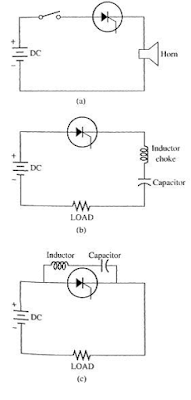
Figure 4 (a) A switch is used to commutate the SCR in a dc circuit by interrupting current flow.  This type of circuit is used to provide control in alarms or emergency dc voltage lighting circuits, (b)  A series of RL resonant circuit circuit used to commutate an SCR and (c) A parallel RL resonant circuit used to commutate an SCR. 
SCRs are also used in the inverter section where the dc voltage is turned back into ac voltage. Since the devices must provide both the positive and the negative half-cycles, a diode is connected in inverse parallel to provide the hybrid ac switch. This combination of devices is not frequently used currently as larger Triacs and Power transistors can do better job in this kind of applications.
Don't miss out on key updates, join our newsletter list here.