Essential components in any controlled automation
system include:
- The actuator (which does the work)
- The controller (which ”tells” the actuator to do the work)
- The sensor (which provides the feedback to the controller so that it knows the actuator is doing work)
An example of a simple controlled automation system
is shown below:
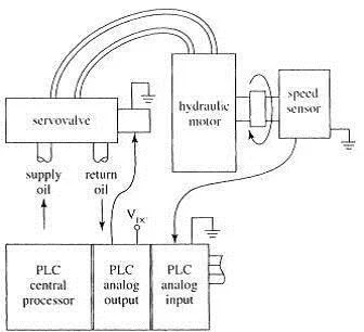
A controlled system may either be analog controlled
system or digital controlled system. Let's consider the following analog controlled
system:
The actuator is a hydraulic servovalve and a fluid
motor. The servovalve opens proportionally with the voltage it receives from
the controller and the fluid motor rotates faster if it receives more hydraulic
fluid. There is a speed sensor connected to the motor shaft, which outputs a
voltage signal proportional to the shaft speed. The controller is programmed to
move the output shaft at a given speed until a load is at given position. When
the program requires the move to take place, the controller outputs an
approximately correct voltage to the servovalve, then monitors the sensor’s
feedback signal. If the speed sensor’s output is different from expected i.e.
indicating wrong motor speed, the controller increases or decreases the voltage
supplied to the servovalve until the correct feedback is achieved. The motor
speed is controlled until the move finishes. As with any other control system,
the program may include a function to notify a human operator if speed control
isn’t working.
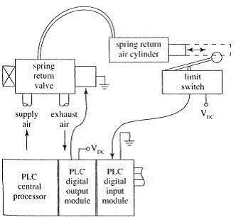
Having looked at analog controlled system above, let's now consider an example of a digital controlled system:
The above figure represents a simple digital
controlled system in which the actuator consists of a pneumatic valve and a
pneumatic cylinder that must be either fully extended or retracted. The
controller is a PLC that has been programmed to extend the cylinder during some
more complicated process and to go on to the next step in the process only
after the cylinder extends. When it is time to extend the cylinder, the PLC
supplies voltage to the valve, which should open to provide air to the
cylinder, which then extend. If all goes well, after a short time the PLC will
receive a change in voltage level from the limit switch, allowing it to execute
the next step in the process. If the voltage from the switch does not change
for any reason ( faulty valve or cylinder or switch, break in a wire,
obstruction preventing full cylinder extension etc.), the PLC will not execute
the next step. The PLC may even be programmed to turn on a “fault” light when
such a delay occurs.
Don't miss out on our Industrial Instrumentation & Automation updates, join our Newsletter list here.
Don't miss out on our Industrial Instrumentation & Automation updates, join our Newsletter list here.


No comments:
Post a Comment