Showing posts with label Industrial Control. Show all posts

Thursday, August 15, 2019

How a VFD works and when to use it


Did you know you could save on energy consumption and costs by using a VFD? You can also tighten your processes, increase production, reduce maintenance, and extend the life of your equipment.

But what is a VFD, you ask? Let’s take a look.

Defining VFD

VFD stands for variable frequency drive. It’s a motor controller for electric motors. VFDs are also known as adjustable speed drives, adjustable frequency drives, AC drives, microdrives, inverters, and variable speed drives.

The word “frequency” in the name relates to the frequency of the power delivered to the motor, which is measured in hertz. Changing the frequency changes the speed of the motor shaft.  If your electric motor doesn’t need to run at full speed for the entire process, you can save some juice and some wear and tear by installing a VFD to vary the speed of the motor.

A variable frequency drive can also get a motor started and ramp it up to speed at a controlled acceleration rate. This makes the start-up smooth, while also saving on electricity and motor life.

A VFD allows one motor to be used for processes that may require or allow different speeds.
Variable Speed Drive in Operation
Variable Speed Drive


How Does a VFD Operate?

A VFD converts fixed frequency AC line voltage to DC, then makes new AC at whatever voltage and frequency are needed to run the motor at the desired speed. The VFD consists of a converter section, a filter section, an inverter section and control section. 
  • The Control section operates the entire VFD, monitors the VFD and motor for safe operation, and interact with the machine operator or automation control system. 
  • The Converter uses diodes and/or SCRs to change AC utility power to DC
  • The Filter ''Cleans'' the DC power with inductors and capacitors
  • The Inverter makes new AC power for the motor using transistors as switches

Those switches are what allow the VFD to function at different speeds. The transistorized switches let the VFD adjust the frequency and voltage of the power supplied to the motor. As the frequency changes, so does the motor speed.

What’s It For?

Anytime you have a system run by an AC electric motor, you may have a need for a VFD. For example, a common use is controlling the speed of a water pump. If the pump is part of a water treatment process, a low demand for water can mean that the water doesn’t exit the plant at the same speed it enters for treatment.

To slow down the supply-side, a VFD is used to slow the water pump.

As mentioned before, a VFD can be used to get a motor started and smoothly accelerate it to operating speed. Energy usage is reduced if operating speed is below full speed.  There is less strain on the motor, less wear and tear on the machinery, and it doesn't just start with a jolt. Using VFDs on conveyors and belts eliminates those jerky starts and increases throughput without damaging equipment.

VFDs can be regulated with a PLC instead of manual adjustment. It’s an easy way to automate a repetitive task and reduce labor cost.

A VFD is a handy little gadget that can help you tighten your process controls, increase production, and minimize mistakes. Your maintenance and repair needs go down, and so does your electricity bill. At the end of the shift, your company has made a little more money than it did before.
You can also read: 


Don't miss out on key updates, join our newsletter list here.
About the Author:
With over 25 years of experience in the industrial automation repair industry, Jeff Conner is the Dallas Service Manager for Control Concepts and serves on the Advisory Committee for the Electronics Technologies Department at Texas State Technical College.
Control Concepts helps design, fabricate, install, test, and program control systems. They service almost any brand of control found in automated systems and can send an experienced technician anywhere, wherever one is needed 24 hours a day, 7 days a week.

Friday, May 3, 2019

Turning Fork Level Switches

This level switch uses a metal tuning fork structure to detect the presence of a liquid or solid (powder or granules) in a vessel.
Turning Fork Level Switch
An electronic circuit continuously excites the tuning fork, causing it to mechanically vibrate. When the prongs of the fork contact anything with substantial mass, the resonant frequency of the structure dramatically decreases. The circuit detects this change and indicates the presence of material contacting the fork. The fork’s vibrating motion tends to shake off any accumulated material such that this style of level switch tends to be resistant to fouling.
You can also read: Ultrasonic Level Switches
Don't miss out on key updates, join our newsletter list here.

Tuesday, March 19, 2019

Types of Signal Converters Commonly used in Industrial Control


Signal converters change a signal from one form to another. In most cases, we have standard inputs and output ranges.
Types of signal converters

Most signal converters have two adjustments-zero and range.
Examples of Signal converters
Nozzle-flapper and differential pressure cells
The nozzle-flapper system is widely used in D.P. Cells. An example is shown below, that converts differential pressure (e.g. from a differential Pressure flow meter into a standard pneumatic signal). This is widely used in the control of air operated pipeline valves.
Flapper Nozzle System

The bellows respond to the differential pressure and moves the lever. This moves the flapper towards or a way from the nozzle. The air supply passes through a restrictor and leaks out of the nozzle. The output pressure hence depends on how close the flapper is to the end of the nozzle. The range of the instrument is adjusted by moving the pivot and zero position is adjusted by moving the relative position of the flapper and nozzle. This system is used in a variety of forms. Instead of bellows, a bourdon tube might be used and this is operated by an expansion type temperature sensor to produce a temperature-pneumatic signal converter.
Current/Pressure conversion 
The figures below show typical units for converting 4-20 mA into 0.2-1 bar or 3-15 psi. They contain adjustments for range and zero. They are widely used for converting the standard pneumatic and electric signals back and forth. They can also be adjusted to work with non standard inputs to convert them into a standard form.
Current to Pressure Converter (C/P)
Current to Pressure Converter

Pressure to Current Converter (P/C)
Pressure to Current Converter

Electric D.P. Cells
They provide the same functions as the pneumatic versions but they are given an output of 4-20 mA using electrical pressure transducers. They are typically used with D.P. Flow meters.
Differential Pressure Transmitter

Analogue -Digital Converters
Analogue to digital conversion is a process of turning an analogue voltage or current into a digital pattern which can read by a computer and processed, this is done by analogue -digital converters.  Lets look at the Binary Numbers, a number may be represented in digital form by simply setting a pattern of voltages on a line high or low. It is normal to use 4, 8, 16 or 32 lines. An 8 bit binary pattern is shown in the below figure:
Binary Numbers
The total pattern is called a word and the one above is an 8 bit word. The pattern may be stored in an 8 bit register. A register is a temporary store where the word may be manipulated. The Bit zero is called the least significant bit (LSB) and the bit with highest value is called the most significant bit (MSB). Each bit has a value of zero when off (LOW) or the value shown when on (HIGH). The maximum value for an 8 bit word is 255.
Digital to Analogue Converters
These are devices for converting a binary number into an analogue voltage. The change in the binary value from zero to a maximum corresponds with a change in the analogue value from 0 to maximum.
One of the manufacturers of signal converters is Omega.
Don't miss out on key updates, join our newsletter list here.

Thursday, December 13, 2018

Types of Proximity Sensors used in Industrial Control

Almost every automated manufacturing operation has sensors that ensure that the system is working correctly.
Examples of Sensors that are used in industrial control are:
Non-Contact Presence Sensors (Proximity Sensors)
Contact sensors are often avoided in automated systems because wherever parts touch there is wear and a potential for eventual failure of the sensor. Automated systems are increasingly being designed with non-contact sensors. The three most common types of non-contact sensors in use today are:
  • Inductive proximity sensor
  • Capacitive proximity sensor
  • Optical proximity sensor

The above sensors are actually transducers, but they include control circuitry that allows them to be used as switches. The circuitry changes an internal switch when the transducer output reaches a certain value.
Hall Effect Limit Switches
Hall Effect Limit Switch

The inductive Sensor
This is the most widely used non-contact sensor due to its small size, robustness, and low-cost. This type of sensor can only detect the presence of electrically conductive materials.
The DC power supplied is used to generate AC in an internal coil, which in turn causes an alternating magnetic field. If no conductive materials are near the face of the sensor, the only impedance to the internal AC is due to the inductance of the coil. If however, a conductive material enters the changing magnetic field, eddy currents are generated in that conductive material, and there is a resultant increase in the impedance to the AC in the proximity sensor. A current sensor, also built into the proximity sensor detects when there is a drop in the internal AC current due to increased impedance. The current controls a switch providing the output.

Inductive Sensor
Inductive Sensor

 
Capacitive proximity Sensors
These sensors sense the target objects due to the target’s ability to be electrically charged. This works both on conductors and non-conductors.
Inside the sensor is a circuit that uses the supplied DC power to generate AC, to measure the current in the internal AC circuit, and to switch the output circuit when the amount of AC current changes. Unlike the inductive sensor, the AC does not drive a coil, but instead tries to charge a capacitor. The AC can move current into and out of this plate only if there is another plate nearby that can hold the opposite charge. The target being sensed acts as the other plate.
Capacitive Proximity Sensor

If this object is near enough to the face of the capacitive sensor to be affected by the charge in the sensor’s internal capacitor plate, it will respond by becoming oppositely charged near the sensor, and the sensor will then be able to move significant into and out of its internal plate.
Optical Proximity Sensors
These are widely used in automated systems because they have been available longer and some can fit into small locations. They are commonly known as light beam sensors of the thru-beam type or of the retro-reflective type. A complete optical proximity sensor includes a light source, and a sensor that detects the light. The light source is supplied because it is usually critical that the light be tailored for the light sensor system. The light source generates a light of a particular frequency which is able to be detected by the light sensor in use. Infra-red light is used in most optical sensors. To make the light sensing system more foolproof, most optical proximity sensor light sources pulse the infra-red light on and off at a fixed frequency. The light sensor circuit is designed so that light that is not pulsing at this frequency is rejected.
Optical Sensors
Optical Proximity Sensors

The light sensor is a semiconductor device such as a photo diode which generates a small current when light energy strikes it or more commonly a photo transistor or a photodarlington that allows current to flow if light strikes it.
Some of the manufacturers of proximity sensors include:

Don't miss out on our updates, join our newsletter list here.

Monday, December 10, 2018

Programmable Logic Controllers (PLC)

Programmable logic controllers (PLC) play an important role in automation sector. Various industries like Food & Beverage, Chemical, Petrochemical, Power generation etc.  use PLC.
We have several types of PLC designs:
Compact PLC: This is built by several modules within a single case. The I/O capabilities are decided by the manufacturer and not the user.
Modular PLC: This is built with several components that are plugged into a common rack or bus with extended I/O capabilities. It contains power supply module, CPU and other I/O modules that are plugged together in the same rack, which are from the same manufacturers or from different manufacturers.
Soft PLC: This is an advanced PLC system that consists of compact, rack mounted components such as power supplies, I/O modules and a CPU which embeds a powerful PLC Control software.
Programming Languages of PLC
There are several programming languages used to write programs in a PLC. They include but not limited:
  • Ladder Diagram
  • Instruction List
  • Functional Block Diagram
  • Sequential Function Chart
  • Structured Text

So what are some of the components that make up a Programmable Logic Controllers?
Components that make up a PLC system
PLC  System

Functions of each component:


CPU – This the unit that contains microprocessors
Input and Output Sections – This is where the processor receives information from external devices and communicates information to external devices.
Power Supply Unit– It converts the Main AC voltage to low DC voltage.
Programming device – Used to enter the required program into the memory of the processor.
Memory Unit – This is where the program is stored that is used to control actions.
The Operation of a PLC
Check the input status: First the PLC takes a look at each I/O to determine if it is on or off.
Execute Program: Next the PLC executes the program one instruction at a time. 
Update output status: Finally the PLC updates the outputs. It updates the outputs based on which inputs were on during the first step. 
 
How a PLC system works
The Working of a PLC system

Advantages of PLC:
  • More flexibility
  • Lower cost
  • Increased reliability
  • Faster response
  • Easier to troubleshoot
  • Communication capability
  • Remote control capability

Disadvantages:
  • They can render some jobs redundant
  • They have a high initial cost
  • If a Programmable logic controller stops, then the production stops 

Industrial Applications of PLCs
  • Food and Beverage industry
  • Gas and Water Filling Stations
  • Power Sector
  • Bottling Plants

Some of the Top PLC Brands in the world include:
Don't miss out on our Control and Automation articles, join our Newsletter list here.

Friday, December 7, 2018

How to upgrade your Legacy Equipment for industry 4.0

Scholar and leadership expert Warren Bennis once said, “In life, change is inevitable. In business, change is vital.” This wisdom resonates with every business owner, but none more than the manufacturer.
We are in the midst of a new industrial revolution, one which will significantly impact the manufacturing industry. Experts are calling it Industry 4.0, the fourth wave in the industrial revolution behind steam power, electricity and computing.
According to TechRadar, Industry 4.0 is “the label given to the gradual combination of traditional manufacturing and industrial practices with the increasingly technological world around us.” Industry 4.0 is ushering in a new era of production where automation and data exchange are integrated into the manufacturing process to streamline productivity.
Sounds great, right? It is, if you can upgrade your legacy equipment. Nobody enjoys the process of upgrading, let alone talking about it, but this is a revolution you don’t want to miss. Here’s how you can upgrade your legacy equipment to successfully ride the wave of Industry 4.0. 
Industrial Internet of Things
The Industrial Internet of Things (IIoT) is the interconnection between manufacturing and production equipment. This equipment uses sensors and internet connectivity to communicate with themselves and one another to create a more efficient production output. As a result, equipment can consider factors like stress on the electrical grid and projected weather to determine the most efficient way to operate at any given time.
According to Gartner, a leading research and advisory company, more than half of major new business processes and systems will incorporate some element of the IIoT by 2020. What’s more, McKinsey Global Institute reported that in the last five years, the number of connected machines has grown by 300 percent.
These businesses are onto something; there are many benefits of integrating the IIoT into manufacturing processes. Information gleaned from the IIoT provides access to real-time data and insights on equipment’s performance and use. Operators can also closely track the lifespan of their machinery in order to proactively plan for maintenance and upgrades. IIoT integration also aids in the automation process. Digitally connecting the machinery creates a mesh that seamlessly translates into full automation. Finally, clients can more readily track the progress of their order with insights provided by the IIoT.
Integrating the IIoT with existing equipment can be challenging, but it isn’t impossible. Most legacy equipment can be retrofitted with sensors and other online monitoring devices.
Smart Factories
In the past, many manufacturing facilities relied on Manufacturing Operations Management (MOM) software to integrate the many independent facets of the production process. Unfortunately, this technology is not able to manage production processes in real-time.
Smart Factory software integrates every part of the production process, including production, resources, supply chain, maintenance and human resources, in order to create a single, efficient output.
This technology enables factory managers to examine data once unavailable, informing decisions about production and other business processes. With Smart software, operators can be more responsive to several factors, including resource availability and cost, consumer demand, market fluctuations, and more. 
Wireless HART network
An Example of Wireless HART mesh network

Digital Supply Chains
Digital supply chains aren’t simple A to B, B to C, C to D processes. In these systems, relationships between different parts of the overall production process are affected by changes or events elsewhere in the system and able to adapt to those changes.
To create a truly digital supply chain, the facility must consider all factors that could potentially impact each part of the supply chain, all the while remedying any issues that may impede the supply chain from operating as designed. Insights from a digital supply chain give manufacturers a real-time overview of every link in the supply chain. As a result, they can quickly respond to problems and simulate scenarios to proactively plan for the future.
To do this well, factories must integrate every step of the product life cycle. This includes everything from sourcing and shipping raw materials, to ordering packaging, advertising the product, and scheduling employees on the factory floor. The digital supply chain system acknowledges that creating a product isn’t black and white. It is a highly sophisticated process that involves many interconnected variables.
Industry 4.0 is here to stay. Upgrades can cause growing pains, but in the end, change is almost always a good thing. Be a part of the next industrial revolution. Integrate your equipment and transform your business.
About the Author:
Page Long is the Marketing Operations Director at PDF Electric & Supply, which is based out of Cary, NC. PDF Electric & Supply is an automation supplier specializing in Legacy GE PLCs.
Don't miss out on our updates on Industrial automation and Control, join our newsletter list here.

Tuesday, December 4, 2018

How to Troubleshoot Servo Drives

Servo drives are used to control devices including robotics, model airplanes, aerospace technology and multiple industrial applications. The drive is a component in a closed-loop system, and uses an amplified control signal to send power to the device motor. They are primarily used to control the output torque, speed and position of a motor shaft.
Most servo drives in use in 2017 are digital, and like all other electronic equipment, they can malfunction at the most inconvenient times. A breakdown can disrupt an entire production schedule and cause significant loss of revenue, or it can cause problems like overheating and result in damage to the systems it supports.
Common Problems with Servo Drives
Most of the typical servo drive issues you’re likely to experience have common causes, which helps to make troubleshooting less frustrating. Here are some malfunctions to watch for:

  •  System instability: If any of your settings are incorrect, the servo drive may not operate correctly. There are numerous parameters to check related to motor tuning as well as speed and current loops.   If you’re getting noise transmitted into the control wiring, you’re likely to see erratic movement of the motor shaft.
  • Inability to reach the right levels of acceleration or deceleration: This can occur for several reasons, such as when the servo amplifier’s capabilities are insufficient for the system inertia, or the friction is excessive.
  • Not responding to a velocity command: The reason for a lack of response is usually easily identifiable, and common causes are problems with the control interface, system or motor malfunctions, incorrect voltage supply (or none at all), or the motor thermal protection has tripped.
  • Noise on signal wires: This is typically caused by incorrect wiring or grounding, but can also be caused by electromagnetic interference from nearby equipment.
  • System runs uncontrollably: This issue develops when there are problems with the velocity command signal, when the motor speed/position feedback signal is erratic or missing, or when there is an internal malfunction in the servo drive.
Motor Drive
AN EXAMPLE OF A MOTOR DRIVE SYSTEM

Troubleshooting: What to Look For 
Correct identification of the problem is critical for effective troubleshooting of your servo drives. Here are some tips on how to go about determining causes of common issues, and measures you can take to try and resolve them.
#1: Review the display on the drive. If it doesn’t come up, check the power supply. If you see an alarm on the display, use the instruction manual to investigate the possible causes.
#2: Verify that the feedback device (resolver, encoder, etc.) is functioning properly.  Use an oscilloscope to check waveforms and pay special attention to noise, missing channels, incorrect wave shapes, or low levels. Look for breaks or bad splices in the feedback cable.
#3: Check the line voltage to ensure that the incoming  power to the drive is balanced and the correct voltage. For common DC bus systems, check the intermediate dc voltage as well.  Use an oscilloscope to check for noise, voltage fluctuations, etc.
#4: Don’t forget the possibility of a mechanical problem. Problems such as friction or vibration in the machine can cause issues in the servo drive and motor.
Run all the tests recommended in the manual and record the results for future reference. If these initial measures don’t work, it’s time to consider getting a professional service company to help.
You can also read: Stepper and Servo motors
About the Author
With over 25 years of experience in the industrial automation repair industry, Jeff Conner is the Dallas Service Manager for Control Concepts and serves on the Advisory Committee for the Electronics Technologies Department at Texas State Technical College. Control Concepts offers around the clock service and support anywhere you need it. To learn more, visit http://www.controlconceptstexas.com
For Timely Instrumentation & Automation updates, join our Newsletter List

Tuesday, November 27, 2018

Key Components used in Industrial Control

Understanding the different components involved in a given process control is important especially for its proper application, and troubleshooting. In this article we look at the most common discrete components used in industrial control applications.
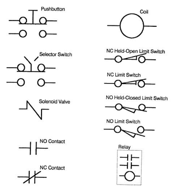
Electrical Symbols of Components commonly used in Industrial Control
COMMON ELECTRICAL SYMBOLS

Contactors
Power consuming devices like Motors are usually controlled by contactors having heavy duty contacts that can switch the power circuits safely. The contactor will be actuated by an electromagnetic solenoid (coil) which pulls the contacts closed when energized. They have an arc-suppressing cover to quench the arc formed when the contacts open under load. Note that AC contactors should never be used to break the current of a loaded DC power circuit. It is more difficulty to quench the arc from a DC power load because there is no AC  ''zero crossing'' to interrupt the current flow. DC contactors are designed to specifically handle DC current. You will find they have embedded magnets, or special blow-out coils that are used to stretch the arc long enough to break the DC current flow.
Devices using AC solenoids will have one or more single turn coil (s), called a shading ring, embedded in the face of their magnetic armature assembly. When the solenoid is energized, the magnetic field has continuous reversals matching the alternating current that is been applied. This will produce a noticeable hum or chatter because the magnetic structure is not energized continuously. As the magnetic field reverses, it induces a current in the shading ring, which in turn produces a secondary reversing magnetic field. The secondary field is out of phase with that of the applied power, and holds the armature faces sealed continuously between power reversals, and minimizes the noise. Over time, shading rings tend to crack from the pounding of the armature faces. When this happens, the solenoid will become very noisy, coil current will increase, and premature failure will result. In an emergency, one can remove the damaged ring and replace it temporarily with a shorted turn of copper wire.
Solenoids
Solenoids are used to actuate brake/ clutch mechanisms, hydraulic valves, air valves, steam valves or other devices that require a push-pull button. Some solenoids can be quite large, requiring contactors rated for their high current draw. Smaller pilot valves may draw no more current than a simple relay. Some heavy duty units operate on DC current. The DC solenoids are often specified for operation in dirty or corrosive areas because current is controlled by circuit resistance, and will not rise if the air-gap is fouled. AC solenoids depend upon the impedance of the circuit. If the air-gap is not sealed properly, inductance reactance is reduced and coil will draw excess current and over-heat. Shading rings must also be switched for possible failures.
Relays
Relays have a similar construction to contactors, but since they switch low-current logic signals, they do not have a requirement for the heavy-duty contacts and arc-suppression hardware. Most relays contacts have AC continuous ratings of no more than 10 A. They can close on an inrush current of 150%, but only break 15% at 120 volts AC (vac). A NEMA A600 rating limits the in-rush to 7200 volt-amperes (va), and a circuit breaking rating of 720 volt-amperes. As higher voltages are used, the current capacity goes down proportionately. This difference in make and break ratings closely matches the typical ratio of inrush and holding currents of AC control coils. AC coils have relatively low resistance, allowing high in-rush currents. As the coil is energized, the AC current builds up inductive reactance. Total impedance (ohms), the vector sum of resistance and reactance, limits the continuous holding current. The ratio of in-rush to holding current is often 5:1 or more. Maximum impedance is attained when the air gap in the magnetic armature assembly has sealed closed. A failure to close this gap will reduce the inductive reactance, allowing more current, which will overheat the coil, causing premature coil failure. A shading ring fracture will also lead to overheating and coil failure.
The same 10A contacts are only rated at 0.4 A DC, at 125V, and 0.2 A DC at 250 V (50 va) because the small air-gaps are not adequate to break a sustained DC arc. Voltages for DC logic controls seldom exceed 24 volts with typical current in the milliamp ranges.
Relays may have multiple coils for latching and unlatching of the contacts. Contacts may be normally open (NO), and or normally closed (NC). The number of contacts usually varies from 1-8. Some relays use contact cartridges which can be converted for either NO or NC operation. Most standard relays will have totally isolated contacts. Some miniature relays have type ”C” contacts where a NO and NC contact share a common terminal. This construction requires careful planning to match the schematic wiring diagram to actual relay construction.
Occasionally the required load on relay contacts may be slightly higher than their normal rating. One can increase the current capacity by connecting contacts in parallel, and improve the arc suppression by connecting multiple contacts in series. When multiple contacts are used this way, they should be on the same relay, because relay coils operating in parallel may have a slight difference in their time-constant.  If one relay closes late, its contacts will take all the inrush punishment. If a relay opens early, it will suffer more damage from breaking most of the full load current.
Timers
Timers are a type of relay that have pneumatic or electronic, time contacts to meet various sequencing requirements. They may be, ”stand-alone” relays or attachments to standard relays. On-delay timers actuate the contacts at a preset time after the coil is energized, and reset instantly with power off.  Off-delay times actuate the contacts instantly when energized, and reset a preset time after de-energizing. NO and/or NC contacts may be time-closed or time-opened. Many timers also include instantaneous contacts, actuated with no time delay. Instantaneous contacts may also be added as a modification kit in some cases to stand-alone timers.
The coils of contactors and relay may be rated at a different voltage than the circuits being switched. This provides isolation between the low voltage logic circuits and higher voltages power circuits.
Push Buttons
Push-buttons may have a single contact block, or an assembly of multiple contacts depending upon the complexity of the requirement. Most push-buttons have a momentary change of state when depressed, then return to normal when released. Some may have a push-pull actuator that latches in each position. They are often used as a control-power master-switch with a Pull-on/Push-off action.
Selector Switches
Many selector switches have the same construction as push buttons, except that the contacts are actuated by rotating a handle or key-switch. The rotating cam may be arranged with incremental indices so that multiple positions and contact patterns can be used to select exclusive operations. Contacts of push-buttons, selector switches, and limit switches usually have the same rating as the logic relays 10A continuous at 120 (vac).
Limit Switches
Mechanical limit switches have many configurations. Most will have both NO and NC contacts available. The contacts are switched when the layer arm is rotated a few degrees by a moving cam or slider. The conventional drawing will show the contact conditions when the machine is un-powered and at rest. It is assumed that the cam will normally strike the arm on the switch to change the state of the contact(s).
Please don't miss out on Instrumentation & Automation updates, join our Newsletter list here.
Non-Contact Limit Switches
There are a number of electronic limit switches that are used where it is not practicable to have an actuator arm physically contact a product or machine part. The switches include: Photocells, and Proximity switches (inductive, magnetic, and capacitive). In each case, a control signal is activated whenever an object enters its operating field. These devices require additional wiring to energize their power.