Showing posts with label Control Systems. Show all posts

Monday, July 29, 2019

Why you should modernize your Relay Control System with a PLC

If you are still running a hard-wired relay control system, it may be time to consider modernizing with programmable logic controllers, or PLCs. PLCs have gotten smaller and more efficient over the years, and they can replace a complex relay system and provide a host of benefits.


Defining PLCs

A programmable logic controller is what it sounds like - a small, special-use computerized control device used in industrial systems. It handles sequential controls, counters, timers, and more. PLCs are more widely used than special-purpose digital computers and have found a place in industrial manufacturing and civil applications.

A PLC continuously monitors input values from sensors, operator controls, etc. and produces outputs to operate machinery based on programming.

How Does a PLC Work?

A PLC is made up of a CPU module, a power supply, and one or more I/O modules. There is no hard drive since the program is stored in internal memory.  A touch screen or other HMI (Human Machine Interface) is optional. The PLC stays inside a control panel and uncomplainingly does its job.

It performs several steps as part of a typical scan cycle:

  • Cycles the operating system and monitors time
  • Reads data from the input module and checks all input statuses
  • Executes user or application program
  • Performs all internal diagnostics and communication tasks
  • Writes data into the output module

As long as the PLC is on, it repeats the cycle until the programming or process comes to an end.
Programmable Logic Controllers


The Benefits of PLCs

One benefit has already been mentioned. A PLC is used across multiple industries and in smaller machinery. But there are other benefits as well. PLCs are:

  • Robust and durable
  • Easy to program
  • Reliable 
  • Easy to use

The I/O module doesn’t even need to be near the CPU. They can be miles apart and still operate connected by data cables. Your PLC isn’t stuck to a single cabinet or building. A PLC can have more than just digital inputs & relay outputs. Improvements over the years have given PLCs the ability to work with a wide variety of analog signals as well as Ethernet and serial communications protocols.

PLCs give your production lines flexibility that you don't get with relays. If you need to retool your line, you can easily reprogram your PLCs to handle the new process.

PLCs are found in such industries as chemical, automotive, steel, food/beverage and more.

Why you should modernize your Relay Control Systems with a PLC

As you have probably experienced, relays use a ton of electricity. They take up space, and they’re noisy and tend to fail a lot. All those electrical connections between relay & socket & interconnecting wires mean more downtime for maintenance. Mechanical relay systems fail more often than PLCs.

If all you need to do is turn an electrical motor on and off safely, a relay may be all you need. But most industrial processes today involve more than that. You need something modern and smart to make your processes energy-efficient and cost-effective.

Modern industry leverages the power of the computer revolution to improve almost every step of any process. Modernize your relay control systems with a PLC, and you'll wonder why it took you so long.

About the Author:

With over 25 years of experience in the industrial automation repair industry, Jeff Conner is the Dallas Service Manager for Control Concepts and serves on the Advisory Committee for the Electronics Technologies Department at Texas State Technical College.

Control Concepts helps design, fabricate, install, test, and program control systems. They service almost any brand of control found in automated systems and can send an experienced technician anywhere one is needed 24 hours a day, 7 days a week.

Thursday, December 13, 2018

Types of Proximity Sensors used in Industrial Control

Almost every automated manufacturing operation has sensors that ensure that the system is working correctly.
Examples of Sensors that are used in industrial control are:
Non-Contact Presence Sensors (Proximity Sensors)
Contact sensors are often avoided in automated systems because wherever parts touch there is wear and a potential for eventual failure of the sensor. Automated systems are increasingly being designed with non-contact sensors. The three most common types of non-contact sensors in use today are:
  • Inductive proximity sensor
  • Capacitive proximity sensor
  • Optical proximity sensor

The above sensors are actually transducers, but they include control circuitry that allows them to be used as switches. The circuitry changes an internal switch when the transducer output reaches a certain value.
Hall Effect Limit Switches
Hall Effect Limit Switch

The inductive Sensor
This is the most widely used non-contact sensor due to its small size, robustness, and low-cost. This type of sensor can only detect the presence of electrically conductive materials.
The DC power supplied is used to generate AC in an internal coil, which in turn causes an alternating magnetic field. If no conductive materials are near the face of the sensor, the only impedance to the internal AC is due to the inductance of the coil. If however, a conductive material enters the changing magnetic field, eddy currents are generated in that conductive material, and there is a resultant increase in the impedance to the AC in the proximity sensor. A current sensor, also built into the proximity sensor detects when there is a drop in the internal AC current due to increased impedance. The current controls a switch providing the output.

Inductive Sensor
Inductive Sensor

 
Capacitive proximity Sensors
These sensors sense the target objects due to the target’s ability to be electrically charged. This works both on conductors and non-conductors.
Inside the sensor is a circuit that uses the supplied DC power to generate AC, to measure the current in the internal AC circuit, and to switch the output circuit when the amount of AC current changes. Unlike the inductive sensor, the AC does not drive a coil, but instead tries to charge a capacitor. The AC can move current into and out of this plate only if there is another plate nearby that can hold the opposite charge. The target being sensed acts as the other plate.
Capacitive Proximity Sensor

If this object is near enough to the face of the capacitive sensor to be affected by the charge in the sensor’s internal capacitor plate, it will respond by becoming oppositely charged near the sensor, and the sensor will then be able to move significant into and out of its internal plate.
Optical Proximity Sensors
These are widely used in automated systems because they have been available longer and some can fit into small locations. They are commonly known as light beam sensors of the thru-beam type or of the retro-reflective type. A complete optical proximity sensor includes a light source, and a sensor that detects the light. The light source is supplied because it is usually critical that the light be tailored for the light sensor system. The light source generates a light of a particular frequency which is able to be detected by the light sensor in use. Infra-red light is used in most optical sensors. To make the light sensing system more foolproof, most optical proximity sensor light sources pulse the infra-red light on and off at a fixed frequency. The light sensor circuit is designed so that light that is not pulsing at this frequency is rejected.
Optical Sensors
Optical Proximity Sensors

The light sensor is a semiconductor device such as a photo diode which generates a small current when light energy strikes it or more commonly a photo transistor or a photodarlington that allows current to flow if light strikes it.
Some of the manufacturers of proximity sensors include:

Don't miss out on our updates, join our newsletter list here.

Monday, December 10, 2018

Programmable Logic Controllers (PLC)

Programmable logic controllers (PLC) play an important role in automation sector. Various industries like Food & Beverage, Chemical, Petrochemical, Power generation etc.  use PLC.
We have several types of PLC designs:
Compact PLC: This is built by several modules within a single case. The I/O capabilities are decided by the manufacturer and not the user.
Modular PLC: This is built with several components that are plugged into a common rack or bus with extended I/O capabilities. It contains power supply module, CPU and other I/O modules that are plugged together in the same rack, which are from the same manufacturers or from different manufacturers.
Soft PLC: This is an advanced PLC system that consists of compact, rack mounted components such as power supplies, I/O modules and a CPU which embeds a powerful PLC Control software.
Programming Languages of PLC
There are several programming languages used to write programs in a PLC. They include but not limited:
  • Ladder Diagram
  • Instruction List
  • Functional Block Diagram
  • Sequential Function Chart
  • Structured Text

So what are some of the components that make up a Programmable Logic Controllers?
Components that make up a PLC system
PLC  System

Functions of each component:


CPU – This the unit that contains microprocessors
Input and Output Sections – This is where the processor receives information from external devices and communicates information to external devices.
Power Supply Unit– It converts the Main AC voltage to low DC voltage.
Programming device – Used to enter the required program into the memory of the processor.
Memory Unit – This is where the program is stored that is used to control actions.
The Operation of a PLC
Check the input status: First the PLC takes a look at each I/O to determine if it is on or off.
Execute Program: Next the PLC executes the program one instruction at a time. 
Update output status: Finally the PLC updates the outputs. It updates the outputs based on which inputs were on during the first step. 
 
How a PLC system works
The Working of a PLC system

Advantages of PLC:
  • More flexibility
  • Lower cost
  • Increased reliability
  • Faster response
  • Easier to troubleshoot
  • Communication capability
  • Remote control capability

Disadvantages:
  • They can render some jobs redundant
  • They have a high initial cost
  • If a Programmable logic controller stops, then the production stops 

Industrial Applications of PLCs
  • Food and Beverage industry
  • Gas and Water Filling Stations
  • Power Sector
  • Bottling Plants

Some of the Top PLC Brands in the world include:
Don't miss out on our Control and Automation articles, join our Newsletter list here.

Tuesday, December 4, 2018

How to Troubleshoot Servo Drives

Servo drives are used to control devices including robotics, model airplanes, aerospace technology and multiple industrial applications. The drive is a component in a closed-loop system, and uses an amplified control signal to send power to the device motor. They are primarily used to control the output torque, speed and position of a motor shaft.
Most servo drives in use in 2017 are digital, and like all other electronic equipment, they can malfunction at the most inconvenient times. A breakdown can disrupt an entire production schedule and cause significant loss of revenue, or it can cause problems like overheating and result in damage to the systems it supports.
Common Problems with Servo Drives
Most of the typical servo drive issues you’re likely to experience have common causes, which helps to make troubleshooting less frustrating. Here are some malfunctions to watch for:

  •  System instability: If any of your settings are incorrect, the servo drive may not operate correctly. There are numerous parameters to check related to motor tuning as well as speed and current loops.   If you’re getting noise transmitted into the control wiring, you’re likely to see erratic movement of the motor shaft.
  • Inability to reach the right levels of acceleration or deceleration: This can occur for several reasons, such as when the servo amplifier’s capabilities are insufficient for the system inertia, or the friction is excessive.
  • Not responding to a velocity command: The reason for a lack of response is usually easily identifiable, and common causes are problems with the control interface, system or motor malfunctions, incorrect voltage supply (or none at all), or the motor thermal protection has tripped.
  • Noise on signal wires: This is typically caused by incorrect wiring or grounding, but can also be caused by electromagnetic interference from nearby equipment.
  • System runs uncontrollably: This issue develops when there are problems with the velocity command signal, when the motor speed/position feedback signal is erratic or missing, or when there is an internal malfunction in the servo drive.
Motor Drive
AN EXAMPLE OF A MOTOR DRIVE SYSTEM

Troubleshooting: What to Look For 
Correct identification of the problem is critical for effective troubleshooting of your servo drives. Here are some tips on how to go about determining causes of common issues, and measures you can take to try and resolve them.
#1: Review the display on the drive. If it doesn’t come up, check the power supply. If you see an alarm on the display, use the instruction manual to investigate the possible causes.
#2: Verify that the feedback device (resolver, encoder, etc.) is functioning properly.  Use an oscilloscope to check waveforms and pay special attention to noise, missing channels, incorrect wave shapes, or low levels. Look for breaks or bad splices in the feedback cable.
#3: Check the line voltage to ensure that the incoming  power to the drive is balanced and the correct voltage. For common DC bus systems, check the intermediate dc voltage as well.  Use an oscilloscope to check for noise, voltage fluctuations, etc.
#4: Don’t forget the possibility of a mechanical problem. Problems such as friction or vibration in the machine can cause issues in the servo drive and motor.
Run all the tests recommended in the manual and record the results for future reference. If these initial measures don’t work, it’s time to consider getting a professional service company to help.
You can also read: Stepper and Servo motors
About the Author
With over 25 years of experience in the industrial automation repair industry, Jeff Conner is the Dallas Service Manager for Control Concepts and serves on the Advisory Committee for the Electronics Technologies Department at Texas State Technical College. Control Concepts offers around the clock service and support anywhere you need it. To learn more, visit http://www.controlconceptstexas.com
For Timely Instrumentation & Automation updates, join our Newsletter List

Sunday, November 18, 2018

Key Features and Applications of Remote Terminal Units (RTU)

Remote Terminal Units also called Remote Telemetry Units or Remote Telecontrol Units are Microprocessor controlled devices that interfaces in the physical world to either SCADA (Supervisory Control and Data acquisition) system or DCS (Distributed and Control system).  They transmit data to a master system and uses messages from the master supervisory system to control objects connected to the system.
They are designed for use in applications in remote locations unattended. These locations may have limited to no power, hence RTUs are designed to consume low power than DCS and PLC & this enables operation on solar power and batteries.
In application where supervision is done from distant central location, the SCADA software sits in the central office connected over a backhaul network typically using radio communication to the RTUs located far away and in most cases geographically spread out. The communication may be interrupted for long periods of time therefore RTUs have on-board  data storage continuing local data collection for more than a month if backhaul communication is lost as well as “history backfill’’ uploading this data once the connection is established again. Report by exception communication mechanisms are often used to minimize backhaul communication using Wide Area Networks e.g. Mobile, Microwave, Satellite.
RTU in Multidrop Communication System

Remote Terminal Units (RTU) Configuration
The RTU configuration software is separate from the HMI (Human Machine Interface) software from a third-party manufacturer i.e. two separate databases. RTU is configured first; next the OPC server is configured. For a native OPC server this happens automatically, but for OPC server from a third-party, manual data mapping is required which can be time-consuming and error prone requiring thorough testing. In most cases native OPC server is preferred. To finalize, the HMI database has to be configured for graphics, alarms, and trends etc.
The 4-20 mA AI and AO cards for a RTU optionally support native HART pass through hence separate HART multiplexer (MUX) hardware and associated work is not required. Native HART pass through AI and AO cards are much easier to integrate and should be specified if 4-20 mA is used. Since RTUs are generally used in very slow monitoring applications that don’t require fast control, some applications do not use the real-time analog 4-20 mA but only the digital HART communication multi-drop topology. This means the field instruments draw less than 4 mA instead of up to 20 mA hence further reducing the overall power consumption.
Applications of Remote Terminal Units (RTU)
Remote terminal units are commonly used in the following applications:
  • Electrical Power Transmission Networks and Associated Equipment.
  • Remote Monitoring of Functions and the whole Instrumentation Network in Oil and Gas (offshore platforms, onshore oil wells, Pump Stations on Pipelines)
  • Water and Wastewater collection and supply networks including the Pumping stations.
Don't miss our on our Industrial Instrumentation updates, join our Newsletter list here.

Monday, November 5, 2018

The Working of Distributed Control Systems

Distributed control system (DCS) is a computerized control system used to control production line in most industries.

Importance of DCS systems
In most cases, products go through many stages in the factory before they reach their final stage. During their passage through those stages, it requires a kind of control in order to adjust the quality of the each product. To adjust quality, you need to control many physical quantities such as Pressure, Temperature, Level, Flow etc. In petrochemical factories and nuclear reactors the control of these parameters is very critical, in fact losing control may lead to an explosion of the whole plant.
So what are the key components that make up a DCS system?
A DCS system consists of:
Programmable Logic Controllers (PLC): These includes input or output modules, CPU, Communication bus, interface module, PS etc.
Operator Station: It is basically human interface machine (HMI) with a monitor, the operator man can view the process in the plant and check if an alarm is present, change any setting, or print reports etc.
Engineering Station: It is used to configure all input & output module, make drawing of anything required and also, monitors an operator station.
The following diagram shows  a Basic Block Diagram of a DCS system:
Block Diagram of a DCS system

The Working of a DCS system
The DCS system receives input signals from other devices, these signals will be processed and analysed by the CPU and based on the result, an action will be taken. There are many sensors and transducers inside the plant which converts physical quantities such as temperature, pressure, level, flow to an electrical quantity and also transmits the electrical signals representation to the DCS system.
The electrical signals could either be analog or digital signals, they could be in either of the two forms: 4-20 mA or 1-5 VDC
The digital signals could either be logic 0 or logic 1
When the PLC receives the analog signals from different transmitters it will convert it to digital signals via input module then pass it to the CPU for processing. The CPU will compare the process measured value (PV) with the set point value (SV). If both the values are not matched, then the DCS will generate an output called manipulated value (MV) to the field via output modules in order to adjust the physical quantity by for example controlling the opening or closing of a valve.
On the face plate, the operator can see both parameters reading SV and PV. The SV can be set to the required level by the operator. DCS system will operate the pump by sending MV signal via output module to fill the tank and continue as long as PV signal received from the transmitter is less than the SV. Once the water level reaches the required point i.e. PV=SV, the DCS will stop the pump and this happen if face-plate mode is AUTO, however in MANUAL mode, the operator can control MV directly and SV pointer will be disabled. This is a simple working of a DCS system. You may find different physical quantities being controlled, it could be the flow rate or pressure in the system.
Some of the leading manufacturers of DCS systems include:

Don't miss out on key updates, join our newsletter list here.

Monday, October 22, 2018

Loop Diagrams


Having looked at the PFD and P & ID Diagrams in our previous posts, we can now discuss the loop diagrams also called the loop sheets. Let's consider the diagram of a compressor surge system shown below:
Loop Diagram
From the loop diagram above we can see more additional instruments that weren’t shown in the PFD and  P & ID: We have 2 transmitters, a controller, and a valve. We also have 2 signal transducers. The first transducer  42a modifies the flow transmitter signal before it goes into the controller. and the second transducer 42b converts the electronic 4-20mA signal into a pneumatic 3-15 PSI air pressure signal. Each instrument  ''bubble''  in a loop diagram represents an individual device, with its own terminals for connecting wires.
The dashed lines represent individual copper wires instead of whole cables. Terminal blocks where these wires connect to are represented by squares with numbers in them. Cable numbers, wire colors, junction block numbers, panel identification and even grounding points are all shown in the loop diagrams.  You can also notice from this loop diagram, the action on each instrument. You will see a box and arrow (pointing either up or down) next to each instrument bubble. An ” up” arrow () represents a direct-acting instrument: one whose output signal increases as the input stimulus increases. A down arrow () represents a reverse-acting instrument, one whose output signal decreases as the input stimulus increases.
All the instruments in this loop are direct-acting with the exception of the pressure differential transmitter PDT-42. Here the down arrow tell us that the transmitter will output a full-range signal (20 mA) when it senses zero differential pressure, and a 0% signal (4 mA) when it sensing a full 200 PSI differential. Excessive pressure drop across the compressor is considered dangerous because it may lead to the compressor surging. For this reason, the controller will naturally take action to prevent surge by commanding the anti-surge control valve to open, because it, “thinks” the compressor is about to surge i.e. the transmitter is intentionally calibrated to be reverse-acting such that any break in the signal wiring will naturally bring the system to its safest condition.
The only diagram that can be more detailed than a loop diagram is the electronic schematic diagram for an individual instrument but then it shows details for that particular instrument alone, thus the loop diagram is the most detailed form of diagram for any control system as a whole and it must contain details omitted by PFDs and P & IDs.            

Saturday, October 20, 2018

Process Flow Diagrams

Instrumentation has its own standardized way of making descriptive diagrams. In this article, we are going to look at the types of diagrams commonly used in industrial instrumentation like the Process Flow Diagrams (PFDs). Essentially we have the following types of instrumentation diagrams:
  • Process Flow Diagrams (PFDs)
  • Process and Instrument Diagrams (P & IDs)
  • Loop Diagrams (Loop Sheets)
  • Functional Diagrams

At the highest level, an instrument technician is interested in the interconnections of process vessels, pipes and flow paths of process fluids therefore he/she would be more likely go for the Process Flow Diagram (PFD), that represent the big picture of the entire process.
At the lowest level, the instrument technician will be more interested in the interconnections of individual instruments including all the wire numbers, terminal numbers, cable types, instrument calibration ranges etc. The proper form of diagram for this level of fine detail is a loop diagram.
Process and Instrument diagrams (P & IDs) lie somewhere in the middle between process diagrams and loop diagrams. A P & ID shows the layout of all relevant process vessels, pipes and machinery, but with instruments superimposed on the diagram showing what gets measured and what gets controlled. You are able to view the flow of the process as well as the flow of information between instruments measuring and controlling the process.
Functional Diagrams are used to document the strategy of a control system. In a functional diagram, emphasis is placed on the algorithms used to control a process, as opposed to piping, wiring, or instrument connections.
An instrument technician has the responsibility of reading the different diagrams when troubleshooting a complex control system. First you begin with a PFD or P&ID to get an overview of the process to see how the major components interact. After identifying which instrument or loop you need to investigate, you go to the appropriate loop diagram to see the interconnection details of that instrument system so that you know where to connect your test equipment and what signals you expect to find when you do so.
Process Flow Diagrams
To help understand better process flow diagrams, we are going to examine the diagrams of a compressor control system. In this process, we assume that water is being evaporated from a process solution under partial vacuum that is being provided by the compressor. The compressor then transports the vapors to a knockout drum where some of them condense into liquid form. As a typical PFD, this diagram shows the major interconnections of process vessels and equipment. But it omits details such as instrument signal lines and auxiliary instruments.
Process Flow Diagram

From the diagram above you might find it hard to determine which control system if any, controls the compressor. All that the PFD shows relating directly to the compressor is a flow transmitter (FT) on the suction line. This level of uncertainty is acceptable for a PFD, because its purpose is merely to show the general flow of the process itself and very little details on Control Instrumentation.
Don't miss out on key updates, join our newsletter list here.

Thursday, October 11, 2018

Introduction to Industrial Automation

Automation is a technique that can be used to reduce costs or improve the quality of products being manufactured. Automation can increase manufacturing speed while at the same time reduce the cost. Automation can also produce products with the same consistent good quality.
Note that Automation is not a straightforward solution to a financial problem however it is a valuable tool that can be used to improve product quality. With improved product quality, you will have lower costs. Producing inexpensive, high quality products is a good policy for any company.
Automation Control/Process Control
Automated processes can be controlled by humans operators, by computers or by a combination of the two. If a human operator is available to monitor and control a manufacturing process, then open loop control system may be acceptable. If a manufacturing process is automated, then it requires a closed loop control.
Open loop control
Fig 1

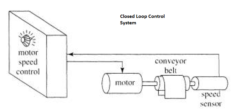
Closed loop control
Fig 2

Fig 1 and 2 above shows examples of open loop and closed loop control. One major difference is the presence of the sensor in the closed loop control system. The motor speed controller uses the feedback it receives from this sensor to verify that the speed is correct, and drives the actuator harder or softer until the correct speed is achieved. In the open loop control system, the operator uses his/her built-in sensors (eyes, ears etc.) and adjusts the actuator (via dials, switches etc.) until the output is correct. Since the operator provides the sensors and the intelligent control functions, these elements do not need to be built into an open loop manufacturing system.
Human operators are more inconsistent than properly programmed computers. Computerized controls, however can also make mistakes, when programmed to do so. Programming a computer to control a complex process is very difficulty. The recent development of affordable digital computers has made automation control possible.
Process control usually implies that the product is produced in a continuous stream. Automation control usually implies a sequence of mechanical steps. A camshaft is an automation controller because it mechanically sequences the steps in the operation of an internal combustion engine. Manufacturing processes are often sequenced by special digital computers known as programmable logic controllers (PLCs), which can detect and can switch electrical signals on and off. Digital computers are ideally suited for automation control type tasks because they consists of circuits each of which can only be either on or off.
Process control is now accomplished using digital computers. Digital controllers may be built into cases with dials and displays making them look like analogue ones. PLCs can also be programmed to operate as analog process controllers. They offer features which allow them to measure and change analog values. Robots and NC equipment use digital computers and a mixture of analog and digital circuit components to control “continuous” variables such as position and speed.
Digital computer control gives us soft automation meaning that they can be reprogrammed easily. Digital computers are also cheap, powerful, fast and compact. They offer many advantages to the automation user. A single digital controller can control several manufacturing processes. The designer only needs to ensure the computer can monitor and control all processes quickly enough and has some excess capacity for future changes.
Soft automation systems can be programmed to detect and to adapt to changes in the work environment or to changes in demand. For example an NC lathe can modify its own speed if it detects a sudden change in the hardness of a raw material being cut. It may also change its own programming in response to a signal from another automated machine requesting a modification in a machined dimension.
Bottom line
Industrial automation is continuously improving, the developments in computers especially with regard to speed has led to more efficient automation systems. As we move into the future, we will see more and better automation systems that have greater performances than current ones.
Don't miss out on key updates, join our newsletter list here.

Monday, September 24, 2018

The use of Smart Sensors in Industrial Control

A smart sensor is the integration of a processor directly into the sensor assembly, which gives direct control of the actuator and digital communication to a central controller i.e. it, allows for the direct conversion of an analog signal to a digital signal, conditioning of the signal, generation of a signal for actuator control, and diagnostics.

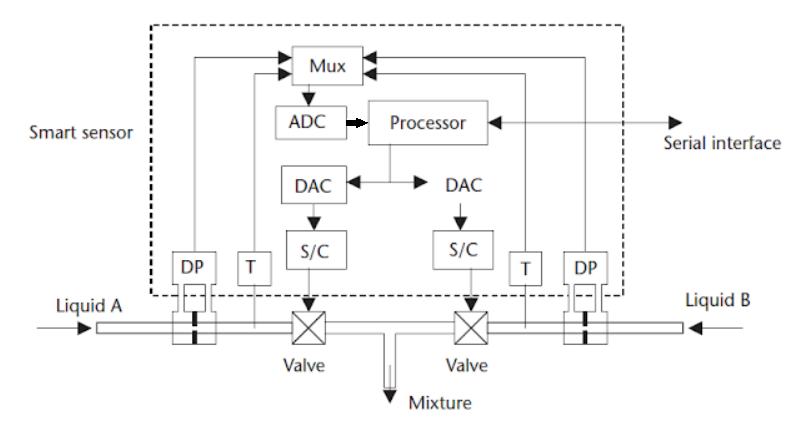
Let’s consider the following diagram:

Smart sensor


The above diagram represents a process where they are mixing two liquids in a fixed ratio, the flow rates of both liquids are monitored using differential pressure sensors (DP). The temperatures of the liquids are monitored to correct the flow rates for density changes and any variations in in the sensitivity of the DP cells using Temperature sensors (T),
The electronics in the smart sensor contains all the circuits necessary to interface to the sensor, amplify and condition the signal, and apply proportional, integral and derivative action (PID).
When the usage is varying, the signals from the sensors are selected in sequence by the multiplexer (Mux), and then converted by the ADC (Analog to Digital Converter) into a digital format for the internal processor.
After signal evaluation by the processor, the control signals are generated, and the DACs (Digital to Analog Converters) are used to convert the signal back into analog format for actuator control.
Communication between the central control computer and the distributed devices is via a common serial bus.
The serial bus or Fieldbus is a single twisted pair of leads used to send the set points to the peripheral units and to monitor the status of the peripheral units. This enables the processor in the smart sensor to receive updated information on factors such as set points, gain, operating mode etc. and to send status and diagnostics information back to the central computer
Smart sensors are available for all the functions required in process control, such as flow, temperature, humidity, pressure and level control.


The implementation of smart sensors has the following advantages over central control systems:
  • Smart sensors use a common serial bus eliminating the need for discrete wires to all sensors, greatly reducing the wiring cost, large cable ducts, and confusion over lead destination during maintenance or upgrades.
  • The smart sensor takes over the conditioning and control of the sensor signal reducing the load on the central control system, allowing for faster system operation.
  • Uniformity in programming means that the program only has to be learned once and new devices can be added to the bus on a plug and play basis.
  • Individual controllers can monitor and control more than one process variable.
  • Smart sensors have a powerful inbuilt diagnostics, which reduces commissioning, and start-up costs and maintenance.
  •        The set points and calibration of a smart sensor are easily changed from the central control computer. 
  •    Direct digital control provides high accuracy, not achievable with analog control systems and central processing.
  •    The cost of smart sensor systems is higher than the conventional systems, but when the cost of maintenance, ease of programming, ease of adding new sensors is taken into account, the long term cost of sensor system is less. 

Limitations of Smart sensors
Since these sensors are connected to a common serial bus, if the bus fails, the total system is down, which is not the case with discrete wiring; this problem can be prevented by use of a redundant backup bus.
Don't miss out on key updates, join our newsletter list here.