Showing posts with label Process Measurement. Show all posts

Sunday, March 10, 2019

The Inputs and Outputs of Process Measurement Instruments Commonly used in Control Systems

Basically when you are doing the troubleshooting of any instrumentation system you assume that every instrument has at least one input and at least one output and that the output(s) should accurately correspond to the input (s). In normal circumstances, if the instrument’s output is not corresponding to its input according to the instrument’s design function, then there could be something wrong with the instrument. Lets consider the inputs of the following examples of  instruments that are commonly used in process control systems:

Process measurement instruments


Controller
Each of the above instruments takes in (input) data and generates the (output) data.  In an instrumentation loop, the output of one instrument feeds into the input of the next. Such information is passed from one instrument to another.
By intercepting the data communicated between components of an instrument system, we are able to locate and isolate faults. For us to able to properly understand the intercepted data, we must understand the inputs and outputs of the respective instruments and the basic functions of those instruments. From the above diagrams, we  are able to highlight the kind of inputs and outputs for each of the instruments indicated.
To be able to check the right correspondence between the instrument inputs and outputs, we must therefore use appropriate test equipment to intercept the signals into and out of these instruments e. g. in case of analogue instruments using 4-20 mA signals we can use the electrical meters capable of measuring the current and voltage.
So what are some of the key considerations when using milliameters to measure loop current?
For you to measure the loop current, you have to break the circuit to connect the milliameter, in series with the current, and which means the current will fall to 0 mA until the meter is connected. Interrupting the current means interrupting the flow of information that is conveyed by that current, be it a process measurement or a command signal to a final control element. This can have adverse effects on the control system unless certain preparations are made before hand. The preparations can be in form of:
  • Informing the personal in charge that signal will be interrupted - state the number of times you intend to do the interruption.
  • For case, where the signal is coming from a process transmitter to a controller, the controller should be placed in manual mode, so that it will not cause an upset in the process. 
  • If the current drives process shutdown alarms, these should be disabled on temporarily basis, so that nothing shuts down upon the interruption of the signal.
  • All process alarms should be temporarily disables so that they do not cause panic.
  • If the current signal to be interrupted is a command signal from a controller to a final control element, the final control element either needs to be manually overridden so as to hold a fixed setting while the signal varies or it needs to be bypassed completely by some other devices (s)
Don't miss out on key updates, join our newsletter list here.


Friday, November 16, 2018

Differential Pressure Transmitters (DP)

One of the most common and useful pressure measuring instrument used in most industrial measurement applications is the differential Pressure transmitter. This device senses the difference in pressure between two ports and outputs a signal representing that pressure in relation to a calibrated range.
Differential Pressure transmitters constructed for industrial measurement applications typically consists of a strong (forged metal) body housing the sensing element(s), topped by a compartment housing the mechanical and/or electronic components necessary to translate the sensed pressure to a standard instrumentation signal e.g. 3-15 PSI, 4-20 mA, Digital Fieldbus codes as shown in the below Diagrams:
Differential Pressure Transmitters

In the below example of Rosemount differential pressure transmitter, the pressure-sensing element is housed in the bottom half of the device (forged-steel structure) while the electronics are housed in the top half (the coloured, round, cast-aluminium structure)
Differential Pressure Transmitter

Every differential Pressure (DP, d/p or ∆P) transmitter has two pressure ports to sense different process fluid pressures. These ports typically have ¼ inch female NPT threads to readily accept connections to the process. One of these ports is labelled “high” and the other is labelled “low’’. This labeling does not necessarily mean that the “high” port must always be at a greater pressure than the “low’’ port. What these labels represent is the effect any increasing fluid Pressure applied to that port will have on the direction of the output signal’s change. Note that, a differential pressure instrument responds only to differential pressure while ignoring the common-mode pressure (gauge pressure common to both ports).
Differential Pressure Transmitters Low and High Ports

The most common sensing element used by modern DP transmitters is the diaphragm. One side of this diaphragm receives process fluid pressure from the “high’’ port while the other receives process fluid pressure from the “low’’ port. Any difference of pressure between the two ports causes the diaphragm to flex from its normal resting (center) position. This flexing is then translated into an output signal by any number of different technologies depending on the manufacturer and the transmitter model.
Differential Pressure (DP) Transmitter Applications
The combination of two differential pressure ports makes the DP transmitter very versatile as a pressure-measuring device. This one instrument can be used to measure pressure differences, positive (gauge) pressures, negative (vacuum), and even absolute pressures, just by connecting the “high” and “low” sensing ports differently.
In every DP transmitter application, there must be some means of connecting the transmitter’s pressure-sensing ports to the points in a process. Metal or plastic tubes (or pipes) work well for this purpose, and are commonly called impulse lines or gauge lines or sensing lines. Typically these tubes are connected to the transmitter and to the process by means of compression fittings which allow for relatively easy disconnection and re-connection of tubes.
Key applications of DP transmitters include:
Measuring Process Vessel Clogging – We may use the DP transmitter to measure an actual difference pressure across a process vessel such as a filter, a heat exchanger, or a chemical reactor. The diagram below shows the use of a DP transmitter to measure clogging of a water filter:
Differential Pressure Transmitter Industrial Applications

From the diagram above, you can see the high side of the DP transmitter connects to the upstream side of the filter and the low side of the transmitter to the down side of the filter. This way, increased filter clogging will result in an increased transmitter output. Since the transmitter’s internal pressure-sensing diaphragm only responds to differences in pressure between “high” and “low” ports, the pressure in the filter and pipe relative to the atmosphere is completely irrelevant to the transmitter’s output signal. The filter could be operating at a line pressure of 15 PSI or 15000 PSI – the only variable the DP transmitter measures is the pressure drop across the filter. If the upstream side is 15 PSI and the downstream side is 14 PSI, the differential pressure will be 1 PSI sometimes labelled PSID, where “D” is differential. If the upstream pressure is 15000 PSI and the downstream pressure is 14,999 PSI, the DP transmitter will still see a differential pressure of just 1 PSID.
Measuring positive gauge pressure – DP instruments can also serve as gauge pressure instruments. If we simply connect the “high” side of a DP instrument to a process vessel using an impulse tube, while leaving the “low” side vented to atmosphere, the instrument will interpret any positive pressure in the vessel as a positive difference between the vessel and the atmosphere. 
Differential Pressure Transmitter Industrial Applications

Most DP instrument manufacturers offer gauge pressure versions of their differential instruments with “high” side port open for connection to an impulse line and the “low’’ side of the sensing element capped off with a special vented flange, effectively performing the same function as in the above figure.
Measuring absolute Pressure – Absolute pressure is defined as the difference between a given fluid pressure and a perfect vacuum. We may build an absolute pressure sensing instrument by taking a DP transmitter and sealing the “low” side of its pressure-sensing element in connection to a vacuum chamber as shown below. This way, any pressure greater than a perfect vacuum will register as a positive difference.
Differential Pressure Transmitter Industrial Applications

Measuring Vacuum – The same principle of connecting one port of a DP device to a process and venting the other works as well as a means of measuring vacuum (Pressure below that of atmosphere). All we need to do is connect the “low” side to the vacuum process and vent the ‘’high” side to the atmosphere as shown below: 
Differential Pressure Transmitter Industrial Applications

Any pressure in the process less than atmospheric will register to the DP transmitter as a positive difference (with P-high   greater than P-Low ). Thus the stronger the vacuum in the process vessel, the greater the signal output by the transmitter.
Inferring liquid level – Liquids generate pressure proportional to height (depth) due to their weight. The pressure generated by a vertical column of liquid is proportional to the column height (h), and liquid’s mass density (ρ), and the acceleration of gravity (ɡ):        P=ρɡh
Differential Pressure Transmitter Industrial Applications

As the liquid in the vessel increases, the amount of hydrostatic pressure applied to the transmitter’s ‘’high’’ port increases in direct proportion. The width of the vessel is irrelevant to the amount of pressure produced only the liquid height (h), density (ρ), and gravity (ɡ) are significant. Thus the transmitters increasing signal represents the height of liquid inside the vessel no matter the size or shape of the vessel.
h = P/ρɡ   
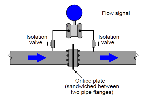
Inferring gas and Liquid Flow – DP transmitters are widely used in measurement of fluid flow. Pressure dropped across a constriction in the pipe varies in relation to flow rate (Q) and fluid density (ρ). So long as fluid density remains fairly constant, we may measure pressure drop across a piping constriction and use that measurement to infer flow rate. The most common form of constriction is the orifice plate. This is a metal plate with a precisely machined hole in the center. As fluid passes this hole, its velocity changes, causing a pressure drop to form.
Differential Pressure Transmitter Industrial Applications

Since both ports of the transmitter connect to the same process line, static fluid pressure within that line has no effect on the measurement. Only differences of pressure between the upstream and downstream sides of the constriction (orifice plate) cause the transmitter to register flow.
Don't miss out on key updates, join our newsletter list here.

Tuesday, November 6, 2018

How Pitot Tubes are used in Flow Measurement

Pitot tube sensors, orifice plates, flow nozzle or venturi tubes are classified as flow measuring devices which utilize differential pressure to measure volumetric flow. 

Pitot Tube Sensor

The Measuring Principle of Pitot Tube
The measuring principle of the pitot tube utilizes the differences between the pressure ridge on the upstream side of a bluff body and the static pressure on its down stream side.
Pitot Tube Measuring Principle

We have differences in pressures at S2 and S1. This difference in pressures is measured, then converted into fluid flow velocity, from this we can derive the volumetric flow using the continuity law with a pipe area A and an average flow velocity. i.e. Q=VA where Q is the volumetric flow, V is the average velocity and A is the pipe area.
Required fluid conditions 
To have good measurements from pitot tube sensors, we need to satisfy the following conditions:
  • The fluid has to completely fill the pipe so that the measured differential Pressure is representative of the volumetric flow. Fluids in partially filled pipes can only be measured if a full pipe can be arranged e.g. by means of siphon. 
  • The fluid must be single-phase. Two phase fluids e.g. water-air mixtures cannot be measured. 
  • The flow has to be sufficiently turbulent. Fluids of laminar nature cannot be measured with pitot tubes.
  • Fluid may contain small particles or bubbles. The pressure generated in front of the sensor apertures causes a deflection of the particles or bubbles. Fluids which tend to crystallize will quickly plug the pressure tubes of the sensor and therefore cannot be measured with pitot tubes. 
  • In steam measurement applications condensate pots are used inside of which a constant transition from steam to condensate and vice versa occurs. The pressure transfer is achieved via water columns. 

Industrial Applications of Pitot Tube Flowmeters
Pitot tube sensors are mainly used to measure the volumetric flow of liquids, gases and steam in closed pipes ranging from½“ to 480“ (DN 20 to DN 12000).
Examples of specific applications include: Precise volumetric flow measurement in batch processes, continuous measurement of liquid ingredients in the process industry, fuel, air, steam and gases as primary energy source as well as in control functions requiring a high degree of stability and repeatability.
Advantages of pitot tubes over orifice plates
  • They have a lower permanent pressure loss as compared to orifice plates. 
  • They have a shorter up/down straight pipe run requirements as compared to orifice plates. 
  • The profile of Pitot tube sensors is designed such that it is symmetrical to the plane between the pressure channels. This arrangement results in the same resistance values and thus the same k-factor with respect to the fluid properties during forward as well as reverse flow. The differential pressures generated by a given flow velocity are the same for flow in either direction. The only differ in the +/- sign. This constitutes an advantage of the orifice plate. Consider the figure below, of an orifice plate which because of its angled downstream corner has different resistances values for forward and reverse flows. It would indicate widely different pressures for the same flow velocity in opposite directions.
Orifice Plate Flow measurement


Some of the manufacturers of Pitot tube flow measurement Instruments, include:

Don't miss out on key updates, join our newsletter list here.

Thursday, October 18, 2018

Advantages and Disadvantages of Pneumatic Instruments


Although we commonly use current to relay information, some critical process measurements use compressed air  to transmit information from one point to another, an example of this can be a petroleum refinery.  Pneumatic instruments find use in some applications that won’t work well with say 4-20 mA current signals due to safety concerns. Pneumatic Instruments still find wide application in industry, although it is increasingly rare to encounter completely pneumatic control loops. 
One of the most common applications for pneumatic control system components is control valve actuation. Not only is compressed air used to create the actuation force in many control valve mechanisms, it is still often the signal medium employed to command the valve’s position. In most cases this pneumatic signal originates from a device called an I/P transducer or current-to-pressure converter, taking a 4-20 mA control signal from the output of an electronic controller and translating that information as a pneumatic 3-15 PSI signal to the control valve positioner or the actuator.
Below is an example of Pressure Transmitter being applied in Pneumatic instrumentation:  
Pressure Transmitter
Let's now look at the advantages and disadvantages of Pneumatic Instruments.
Don't miss out on key updates, join our newsletter list here.
Disadvantages of Pneumatic Instruments Include:

  • Sensitivity to vibration, changes in temperature and mounting position which may affect the calibration accuracy to a far greater degree than electronic instruments.
  • Compressed air is an expensive utility which is much more expensive per equivalent watt-hour than electricity which makes the operational cost of pneumatic instruments far greater than electronic. The installed cost of pneumatic instruments can be quite high as well given the need for special material i.e. Stainless steel, Copper, or Tough plastic tubes to carry air and pneumatic signals to distant locations.
  • The volume of air tubes used to convey pneumatic signals over distances act as a low-pass filter, naturally damping the instrument’s response and thereby reducing its ability to respond quickly to changing process conditions.
So with the above disadvantages, why are the pneumatic instruments still in use today?
The main reason may be due to legacy hence facilities using these pneumatic instruments  and have them in good work conditions, won’t see the need to replace them since in most cases the cost of labor to remove old tubing, install new conduit and configure new (expensive) electronic instruments is often not worth the benefits.
You can also read: Pneumatic Signal Transmission
Advantages of pneumatic Instruments include:

  • Intrinsic Safety of pneumatic field instruments. Instruments that do not run on electricity cannot generate electrical sparks. This is of utmost importance in classified industrial environments where explosive gases, liquids, dusts and powders exist.
  • Pneumatic instruments are also self-purging. The continual bleeding of compressed air from vent ports in pneumatic relays and nozzles acts as a natural clean-air purge for the inside of the instrument, preventing the intrusion of dust and vapor from the outside with a slight positive pressure inside of the instrument case. Pneumatic instruments mounted inside larger enclosures with other devices tend to protect them all by providing a positive-pressure air purge for the entire enclosure.
  •   Some pneumatic instruments can also function in high-temperature and high-radiation environments that would damage electronic instruments.
  •  Pneumatic instruments can also operate on compressed gases besides air. This is an advantage in remote natural gas installations, where the natural gas itself is sometimes uses as a source of pneumatic ”power” for instruments. So long as there is compressed natural gas in the pipeline to measure and to control, the instruments will operate. No air compressor or electrical power source is needed in these installations. All you need is a good filtering equipment to prevent contaminants in the natural gas (Dirt, liquids, Debris) from causing problems within the sensitive instrument mechanisms.

Monday, October 15, 2018

Variable Area Flowmeters


Variable area flowmeters typically feature a vertically positioned measuring cone through which the medium flows from bottom to top, lifting against the weight. We also have the horizontal and inverted (top to bottom) versions that are used where the installation structure doesn't allow for vertical version. 

We have two main types of variable area flowmeters:
  • Float type (Rotameter)
  • Tapered plug type
Float Type
The float is inside a tapered tube as shown below:

Variable Area Flowmeter

The fluid flows through the annular gap around the edge of the float. The friction causes a pressure drop over the float and the pressure forces the float upwards. Because the tube is tapered, the restriction is decreased as the float moves up. Eventually a level is reached where the restriction is just right to produce a pressure force that counteracts the weight of the float. The level of the float indicates the flow rate. If the flow changes, the float moves up or down to find a new balance position.

In case dangerous fluids are used, protection is needed against the tube fracturing. The tube may be made of non-magnetic metal. The float has a magnet on it, as it moves up and down; the magnet moves a follower and pointer on the outside. The position of the float may be measured electrically by building a movement transducer into the float.


Tapered Plug Type
This type has a tapered plug aligned inside a hole or orifice.

Variable Area Flowmeter

A spring holds it in place. The flow is restricted as it passes through the gap and a force is produced which moves the plug. Because it is tapered, the restriction changes and the plug takes a position where the pressure force just balances the spring force. The movement of the plug is transmitted with a magnet to an indicator on the outside.

Industrial Applications of Variable Area Flowmeters
Variable flowmeters are used in various industrial flow measurement applications, e.g.
  • Continuous gas and liquid measurement
  • Measurement of non-conductive media
  • Compressor monitoring
  • Industrial Burner controlling
  • Dry-run protection of pumps
Don't miss out on key updates, join our newsletter list here.

Saturday, October 13, 2018

The working Principle of Thermocouples


When two wires with dissimilar electrical properties are joined at both ends and one junction is made hot and the other cold, a small current is produced proportional to the difference in the temperature.
For example, we have the cold end joined at a sensor millivolt meter, and the hot junction forming the sensor end as shown below:

Thermocouple

Peltier showed that the heat is absorbed at the hot end and rejected at the cold end. Thompson showed that part of the e.m.f. is due to temperature gradient in the wire as well as the temperature difference between the junctions.  Most of thermocouple metals produce a relationship between the two temperatures and the e.m.f. as follows:


Thermocouple Equation showing relationship between two temperatures and e.m.f

The α and β are constants for the type of thermocouple. The relationship is nearly linear over the operating range. The actual characteristics and suitable operating temperatures depend upon the metals used in the wires. The various types are designated in international and national standards. Typical linear operating ranges are shown for standard types. Note, it is important for thermocouples to be standard so that the e.m.f. will always represent the same temperature.

Thermocouple Types

Thermocouples come in several forms, they may be wires insulated from each other with plastic or glass fibre materials. For high temperature work, the wire pairs are put inside a tube with mineral insulation. For industrial uses, the sensor comes in a metal enclosure such as a stainless steel. 

Example of typical thermocouple industrial probes is shown below:
Thermocouple Probes


Instrument Errors and Calibration


In any measurement system, the instruments in use are prone to errors due to aging or manufacturing tolerances. These instrument errors must be stated before taking any measurement. Some of the common terms used when describing the performance of an instrument are:
  • Accuracy – The accuracy of an instrument is often stated as % of the range or full-scale deflection. e.g. A Pressure gauge with a range 0 to 500 kpa and an accuracy of plus or minus 2% full-scale deflection, could have an error of plus or minus 10 kpa. When the gauge is indicating 10 kpa the correct reading could be anywhere between 0 and 20 kpa and the actual error in the reading could be 100 %. When the gauge indicates 500 kpa the error could be 2 % of the indicated reading.
  • Range – The range of an instrument is usually regarded as the difference between the maximum and minimum reading, e.g.  a thermometer that has a scale from 20 to 100 ° C has a range of 80 °C. This is also called the Full scale deflection (f.s.d.).
  • Repeatability – If an accurate signal is applied and removed repeatedly to the system and it is found that the indicated reading is different each time, the instrument has poor repeatability. This is often caused by friction or some other erratic faulty in the system.
  • Stability – Instability will likely occur in instruments involving electronic processing with a high degree of amplification. Causes of this could be environmental factors such as temperature and vibration, e.g. a rise in temperature may cause a transistor to increase the flow in current which in turn makes it hotter and so the effect grows and the displayed reading DRIFTS. In extreme cases, the displayed value may jump about caused by for example a poor electrical connection affected by vibration.
  • Time lag error – This occurs when an instrument takes time for a change in the input to show up on the indicated output. This time may be very small or very large depending upon the system. If the indicated output is incorrect because it has not yet responded to the change, then we have time lag error. When a signal changes a lot and quite quickly e.g. a speedometer, the person reading the dial would have a great difficulty determining the correct value as the dial may be still going up when in reality the signal is going down again.
  • Drift – This occurs when the input to the system is constant but the output tends to change slowly. For example when switched on, the system may drift due to the temperature change as it warms up.
  • Reliability – An instrument in most cases will have a predicted life span. The more reliable it is, the less chance it has of going wrong during its expected life span. The reliability is hence a probability ranging from zero ( it will definitely fail) to 1.0 ( it will definitely not tail).

INSTRUMENT CALIBRATION
Most instruments have a built-in mechanism for making adjustments. These are:
  • The range adjustment
  • The zero adjustment
In order to Calibrate  an instrument an accurate gauge is required. This is likely to be a Secondary standard. Instruments calibrated as a secondary standard have themselves been calibrated against a primary standard.
Procedure
An input representing the minimum gauge setting should be applied. The output should be adjusted to be correct. Next the maximum signal is applied. The range is then adjusted to give the required output. This is repeated until the gauge is correct at the minimum and the maximum values.

You can also read: 

Calibration Errors
Range and zero Error – After obtaining correct zero and range for the instrument, a calibration graph should be produced. This involves plotting the indicated reading against the correct reading from the standard gauge. This should be done in about 10 steps with increasing signals and then with reducing signals. Several forms of error could show up. If zero or range is still incorrect the error will appear as shown figure 1 and 2 below:
Instrument Zero Errror
Figure 1
Instrument Range Error
Figure 2


Hysteresis and Nonlinear Errors – Hysteresis is produced when the displayed values are too small for increasing signals and too large for decreasing signals. This is commonly caused in mechanical instruments by loose gears, linkages and friction. It occurs widely with equipment involving magnetization and demagnetization.  The calibration may be correct at the maximum and minimum values of the range but the graph joining them may not be a straight line ( when it ought to be). This is a nonlinear error. The instrument may have some adjustments for this and it may be possible to make it correct at mid range as shown in figure 3 and 4. 
Hysteresis Error
Figure 3
Linearity Error
Figure 4

Don't miss out on key updates, join our newsletter list here.

Friday, October 12, 2018

Instrumentation Sensors and Transducers


A basic instrumentation system consists of 3 elements:
  • Sensor or Input Device
  • Signal Processor
  • Receiver or output device

A block diagram of a basic instrumentation system is shown below:
Instrumentation System Block Diagram

Most modern analogue instruments work on the following standard signal ranges:
  • Electric 4-20 mA 
  • Pneumatic 0.2 to 1.0 bar which is equivalent to 3 -15 PSI

The old electrical equipment use 0 to 10 v. Pneumatic signals are commonly used in process industries for safety especially when there is a risk of fire or explosion.
The advantage of having a standard range or using digital signals is that all equipment may be purchased ready calibrated. For analogue systems the minimum signal (Temperature, Speed, Force, Pressure etc.) is represented by 4 mA or 0.2 bar or 3 PSI. and the maximum signal is represented by 20 mA or 1.0 bar or 15 PSI.
The physical quantities commonly measured include:
  • Flow rate
  • Temperature
  • Pressure
  • Level
  • Mass or Weight
  • Density
  • Speed
  • Strain
  • Movement, Velocity and Acceleration
  • Acidity/Alkalinity
Sensors may operate simple on or off switches to detect the following:
  • Objects (proximity switch)
  • Hot or Cold (Thermostat)
  • Empty or full (level switch)
  • Pressure high or low (Pressure switch)

The block diagram of a sensor as shown below:
Block Diagram of a sensor

We have different types of sensors used in instrumentation:
  • Temperature transducers e.g. Thermocouple, Resistance Temperature detectors etc. 
  • Pressure transducers e.g. Bourdon Tube
  • Speed transducers e.g. Tachometer, Magnetic pickup & optic types
  • Flowmeters e.g. Positive Displacement meters, Differential Pressure Flowmeters, Turbine etc. 
  • Force sensors: mechanical, hydraulic, electric strain gauge
  • Position sensors: Resistive, Optical, Inductive
  • Depth gauges: Ultrasonic, Pressure Gauge, Electronic level gauge
  • Strain gauges

From the above, we learn that any instrumentation system whether basic or complex, has an input/sensor, a signal processing unit and lastly an output or receiver.

Wednesday, October 10, 2018

How to use "Test" Diodes to measure 4-20 mA Loop Current

We have different ways of measuring 4-20 mA loop current. Normally we use the standard milliammeter to measure the loop current but downside of this method, is you have to break the circuit, at some point to connect the meter in series with the current, which means interrupting the flow of information conveyed by that current. That why we have other methods you can use to measure the loop current without interrupting the process, you can use:
  • Clamp-on milliammeter
  • Test" diodes
  • Shunt resistors

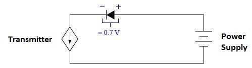
In this article we discuss the use of ''Test'' diodes to measure loop current in process measurement and control systems. The use of rectifying diode that is originally in the loop circuit when it is commissioned to measure 4-20 mA loop signal ensures no interruption. A ”test” diode may be placed anywhere in series within the loop in such a way that it will be forward-biased. During normal operation, the diode will drop approximately 0.7 volts, as it is typical for any silicon rectifying diode when forward biased. To illustrate this, the following schematic diagram shows such a diode installed in a 2-wire transmitter loop circuit:
''Test" Diode being used to measure loop current
Fig 1

If you connect a milliammeter in parallel with this diode, (as shown in Fig 2), however, the very low input resistance of the ammeters, '' shorts past'' the diode and prevents any substantial voltage drop from forming across it.  Without the necessary forward voltage drop, the diode effectively turns off and conducts 0 mA, leaving the entire loop current to pass through the ammeter.
Measuring the loop current with the use of ''test'' diodes
Fig 2
When you disconnect the milliammeter, the requisite 0.7 volt drop appears to turn on the diode, and all the loop current flows through the diode again. From this, you can see there is no interruption meaning that the technician may take current measurements this way with no worries about generating false process variable indications, setting off alarms or upsetting the process.

Such a diode may be installed at the nearest junction box, between terminals on a terminal strip, or even incorporated into the transmitter itself. If you check carefully, some process transmitters have an extra pair of terminals labelled “Test” for this exact purpose. A diode is already installed in the transmitter, and these “Test” terminals serve as points to connect the milliameter across it. An example is shown of a Rosemount differential pressure transmitter:
Rosemount Differential Pressure Transmitter showing ''test'' diode terminals
Fig 3
Take note of the test points labelled “TEST” below and to the right of the main screw terminals where the loop wiring attaches. Connecting an ammeter to these two test points allows for direct measurement of the 4-20 mA current signal without having to undo any wire connections in the circuit.
Transmitters equipped with analog meter movements for direct visual indication of the 4-20 mA signal usually connect the analog milliameter in parallel with such a diode. The reason for doing this is to maintain loop continuity in the event that the fine-wire coil inside the milliameter movement were to accidentally break open.
Don't miss out on key updates, join our newsletter list here.