Showing posts with label Measurement and Control Systems. Show all posts

Sunday, March 10, 2019

The Inputs and Outputs of Process Measurement Instruments Commonly used in Control Systems

Basically when you are doing the troubleshooting of any instrumentation system you assume that every instrument has at least one input and at least one output and that the output(s) should accurately correspond to the input (s). In normal circumstances, if the instrument’s output is not corresponding to its input according to the instrument’s design function, then there could be something wrong with the instrument. Lets consider the inputs of the following examples of  instruments that are commonly used in process control systems:

Process measurement instruments


Controller
Each of the above instruments takes in (input) data and generates the (output) data.  In an instrumentation loop, the output of one instrument feeds into the input of the next. Such information is passed from one instrument to another.
By intercepting the data communicated between components of an instrument system, we are able to locate and isolate faults. For us to able to properly understand the intercepted data, we must understand the inputs and outputs of the respective instruments and the basic functions of those instruments. From the above diagrams, we  are able to highlight the kind of inputs and outputs for each of the instruments indicated.
To be able to check the right correspondence between the instrument inputs and outputs, we must therefore use appropriate test equipment to intercept the signals into and out of these instruments e. g. in case of analogue instruments using 4-20 mA signals we can use the electrical meters capable of measuring the current and voltage.
So what are some of the key considerations when using milliameters to measure loop current?
For you to measure the loop current, you have to break the circuit to connect the milliameter, in series with the current, and which means the current will fall to 0 mA until the meter is connected. Interrupting the current means interrupting the flow of information that is conveyed by that current, be it a process measurement or a command signal to a final control element. This can have adverse effects on the control system unless certain preparations are made before hand. The preparations can be in form of:
  • Informing the personal in charge that signal will be interrupted - state the number of times you intend to do the interruption.
  • For case, where the signal is coming from a process transmitter to a controller, the controller should be placed in manual mode, so that it will not cause an upset in the process. 
  • If the current drives process shutdown alarms, these should be disabled on temporarily basis, so that nothing shuts down upon the interruption of the signal.
  • All process alarms should be temporarily disables so that they do not cause panic.
  • If the current signal to be interrupted is a command signal from a controller to a final control element, the final control element either needs to be manually overridden so as to hold a fixed setting while the signal varies or it needs to be bypassed completely by some other devices (s)
Don't miss out on key updates, join our newsletter list here.


Tuesday, February 5, 2019

The Components that make up a 4-20 mA Current Loop

The 4-20 mA current  loop is an important aspect of process measurement and control circuits. The important components that make up this loop are:
  • The Sensor
  • The Transmitter
  • The Power Source
  • The Loop itself
  • The Receiver

The following diagram shows each component with its function:
Components in a 4-20 mA current loop

This is a simple illustration of a 4-20 mA current Loop System.
 You can also read:

Don't miss out on key updates, join our newsletter list here.

Friday, December 7, 2018

How to upgrade your Legacy Equipment for industry 4.0

Scholar and leadership expert Warren Bennis once said, “In life, change is inevitable. In business, change is vital.” This wisdom resonates with every business owner, but none more than the manufacturer.
We are in the midst of a new industrial revolution, one which will significantly impact the manufacturing industry. Experts are calling it Industry 4.0, the fourth wave in the industrial revolution behind steam power, electricity and computing.
According to TechRadar, Industry 4.0 is “the label given to the gradual combination of traditional manufacturing and industrial practices with the increasingly technological world around us.” Industry 4.0 is ushering in a new era of production where automation and data exchange are integrated into the manufacturing process to streamline productivity.
Sounds great, right? It is, if you can upgrade your legacy equipment. Nobody enjoys the process of upgrading, let alone talking about it, but this is a revolution you don’t want to miss. Here’s how you can upgrade your legacy equipment to successfully ride the wave of Industry 4.0. 
Industrial Internet of Things
The Industrial Internet of Things (IIoT) is the interconnection between manufacturing and production equipment. This equipment uses sensors and internet connectivity to communicate with themselves and one another to create a more efficient production output. As a result, equipment can consider factors like stress on the electrical grid and projected weather to determine the most efficient way to operate at any given time.
According to Gartner, a leading research and advisory company, more than half of major new business processes and systems will incorporate some element of the IIoT by 2020. What’s more, McKinsey Global Institute reported that in the last five years, the number of connected machines has grown by 300 percent.
These businesses are onto something; there are many benefits of integrating the IIoT into manufacturing processes. Information gleaned from the IIoT provides access to real-time data and insights on equipment’s performance and use. Operators can also closely track the lifespan of their machinery in order to proactively plan for maintenance and upgrades. IIoT integration also aids in the automation process. Digitally connecting the machinery creates a mesh that seamlessly translates into full automation. Finally, clients can more readily track the progress of their order with insights provided by the IIoT.
Integrating the IIoT with existing equipment can be challenging, but it isn’t impossible. Most legacy equipment can be retrofitted with sensors and other online monitoring devices.
Smart Factories
In the past, many manufacturing facilities relied on Manufacturing Operations Management (MOM) software to integrate the many independent facets of the production process. Unfortunately, this technology is not able to manage production processes in real-time.
Smart Factory software integrates every part of the production process, including production, resources, supply chain, maintenance and human resources, in order to create a single, efficient output.
This technology enables factory managers to examine data once unavailable, informing decisions about production and other business processes. With Smart software, operators can be more responsive to several factors, including resource availability and cost, consumer demand, market fluctuations, and more. 
Wireless HART network
An Example of Wireless HART mesh network

Digital Supply Chains
Digital supply chains aren’t simple A to B, B to C, C to D processes. In these systems, relationships between different parts of the overall production process are affected by changes or events elsewhere in the system and able to adapt to those changes.
To create a truly digital supply chain, the facility must consider all factors that could potentially impact each part of the supply chain, all the while remedying any issues that may impede the supply chain from operating as designed. Insights from a digital supply chain give manufacturers a real-time overview of every link in the supply chain. As a result, they can quickly respond to problems and simulate scenarios to proactively plan for the future.
To do this well, factories must integrate every step of the product life cycle. This includes everything from sourcing and shipping raw materials, to ordering packaging, advertising the product, and scheduling employees on the factory floor. The digital supply chain system acknowledges that creating a product isn’t black and white. It is a highly sophisticated process that involves many interconnected variables.
Industry 4.0 is here to stay. Upgrades can cause growing pains, but in the end, change is almost always a good thing. Be a part of the next industrial revolution. Integrate your equipment and transform your business.
About the Author:
Page Long is the Marketing Operations Director at PDF Electric & Supply, which is based out of Cary, NC. PDF Electric & Supply is an automation supplier specializing in Legacy GE PLCs.
Don't miss out on our updates on Industrial automation and Control, join our newsletter list here.

Wednesday, December 5, 2018

Key Considerations when Specifying Displacer Level Transmitters

Displacer level transmitter is used in Process measurements of liquids across many process industries. In this article we discuss the Principle of operation and industrial level applications that displacer transmitter technology offers.
Principle of Operation
Displacer Level Transmitter

Operation is based on buoyancy force. The buoyancy force works on the displacer which will vertically move in (increasing liquid level) and out (decreasing liquid level) the linear differential transformer (LVDT). Due to this movement, voltages are induced in the secondary winding of the LVDT. These signals are then processed in the electronic circuitry and used to control the output signal.
Industrial Applications
Displacer transmitters are ideal solution for liquids or slurries, clean or dirty and light hydrocarbons to heavy acids with a specific gravity (SG) of 0.23 to 2.20.
Displacer transmitter technology works well in a variety of vessels including process & storage, bridles, bypass chambers, interfaces, sumps and pits up to unit pressure and temperature ratings. They can also handle most liquid conditions including varying dielectric, vapors, turbulence, foam, buildup, bubbling or boiling and high fill/empty rates.
Some of the specific industrial applications include:
Boiler control – The displacer unit provides a stable output signal for valve control on turbulent surface applications, such as feed water heaters, flash tanks, and reactors. 
Interface control on storage tanks – The displacers are tolerant of emulsions. They can track towards middle of emulsion, and are tolerant of unstable interface. They also ignore vapor/liquid interface point above displacer.
Mixing Tank – The displacer transmitter can also be used in harsh production environments like those in a mixing tank. It provides a stable output, easier to configure and is resistant to heavy surging caused by the mixer.
Water elevation – The displacer can be used to maintain a water elevation at a given height by sending out a proportional 3-15 PSIG signal (over a 14 ″ control band) to a control valve to maintain water level at midpoint by regulating the water flow rate out of the separator. The control valve is fully open at 15 PSIG input and fully closed at 3 PSIG input.
In Summary the advantages and limitations of Displacer transmitter include:
Advantages
  • Stable signal in turbulent applications
  • High Pressure/Temperature capabilities
  • No flexure of pressure boundary part

Limitations
  • Shifting SG can affect this technology

Some of the manufactures of Displacer level transmitters include:
Sources: Magnetrol
Don't miss out on our Instrumentation updates, join our newsletter list here

Tuesday, December 4, 2018

How to Troubleshoot Servo Drives

Servo drives are used to control devices including robotics, model airplanes, aerospace technology and multiple industrial applications. The drive is a component in a closed-loop system, and uses an amplified control signal to send power to the device motor. They are primarily used to control the output torque, speed and position of a motor shaft.
Most servo drives in use in 2017 are digital, and like all other electronic equipment, they can malfunction at the most inconvenient times. A breakdown can disrupt an entire production schedule and cause significant loss of revenue, or it can cause problems like overheating and result in damage to the systems it supports.
Common Problems with Servo Drives
Most of the typical servo drive issues you’re likely to experience have common causes, which helps to make troubleshooting less frustrating. Here are some malfunctions to watch for:

  •  System instability: If any of your settings are incorrect, the servo drive may not operate correctly. There are numerous parameters to check related to motor tuning as well as speed and current loops.   If you’re getting noise transmitted into the control wiring, you’re likely to see erratic movement of the motor shaft.
  • Inability to reach the right levels of acceleration or deceleration: This can occur for several reasons, such as when the servo amplifier’s capabilities are insufficient for the system inertia, or the friction is excessive.
  • Not responding to a velocity command: The reason for a lack of response is usually easily identifiable, and common causes are problems with the control interface, system or motor malfunctions, incorrect voltage supply (or none at all), or the motor thermal protection has tripped.
  • Noise on signal wires: This is typically caused by incorrect wiring or grounding, but can also be caused by electromagnetic interference from nearby equipment.
  • System runs uncontrollably: This issue develops when there are problems with the velocity command signal, when the motor speed/position feedback signal is erratic or missing, or when there is an internal malfunction in the servo drive.
Motor Drive
AN EXAMPLE OF A MOTOR DRIVE SYSTEM

Troubleshooting: What to Look For 
Correct identification of the problem is critical for effective troubleshooting of your servo drives. Here are some tips on how to go about determining causes of common issues, and measures you can take to try and resolve them.
#1: Review the display on the drive. If it doesn’t come up, check the power supply. If you see an alarm on the display, use the instruction manual to investigate the possible causes.
#2: Verify that the feedback device (resolver, encoder, etc.) is functioning properly.  Use an oscilloscope to check waveforms and pay special attention to noise, missing channels, incorrect wave shapes, or low levels. Look for breaks or bad splices in the feedback cable.
#3: Check the line voltage to ensure that the incoming  power to the drive is balanced and the correct voltage. For common DC bus systems, check the intermediate dc voltage as well.  Use an oscilloscope to check for noise, voltage fluctuations, etc.
#4: Don’t forget the possibility of a mechanical problem. Problems such as friction or vibration in the machine can cause issues in the servo drive and motor.
Run all the tests recommended in the manual and record the results for future reference. If these initial measures don’t work, it’s time to consider getting a professional service company to help.
You can also read: Stepper and Servo motors
About the Author
With over 25 years of experience in the industrial automation repair industry, Jeff Conner is the Dallas Service Manager for Control Concepts and serves on the Advisory Committee for the Electronics Technologies Department at Texas State Technical College. Control Concepts offers around the clock service and support anywhere you need it. To learn more, visit http://www.controlconceptstexas.com
For Timely Instrumentation & Automation updates, join our Newsletter List

Friday, November 16, 2018

Differential Pressure Transmitters (DP)

One of the most common and useful pressure measuring instrument used in most industrial measurement applications is the differential Pressure transmitter. This device senses the difference in pressure between two ports and outputs a signal representing that pressure in relation to a calibrated range.
Differential Pressure transmitters constructed for industrial measurement applications typically consists of a strong (forged metal) body housing the sensing element(s), topped by a compartment housing the mechanical and/or electronic components necessary to translate the sensed pressure to a standard instrumentation signal e.g. 3-15 PSI, 4-20 mA, Digital Fieldbus codes as shown in the below Diagrams:
Differential Pressure Transmitters

In the below example of Rosemount differential pressure transmitter, the pressure-sensing element is housed in the bottom half of the device (forged-steel structure) while the electronics are housed in the top half (the coloured, round, cast-aluminium structure)
Differential Pressure Transmitter

Every differential Pressure (DP, d/p or ∆P) transmitter has two pressure ports to sense different process fluid pressures. These ports typically have ¼ inch female NPT threads to readily accept connections to the process. One of these ports is labelled “high” and the other is labelled “low’’. This labeling does not necessarily mean that the “high” port must always be at a greater pressure than the “low’’ port. What these labels represent is the effect any increasing fluid Pressure applied to that port will have on the direction of the output signal’s change. Note that, a differential pressure instrument responds only to differential pressure while ignoring the common-mode pressure (gauge pressure common to both ports).
Differential Pressure Transmitters Low and High Ports

The most common sensing element used by modern DP transmitters is the diaphragm. One side of this diaphragm receives process fluid pressure from the “high’’ port while the other receives process fluid pressure from the “low’’ port. Any difference of pressure between the two ports causes the diaphragm to flex from its normal resting (center) position. This flexing is then translated into an output signal by any number of different technologies depending on the manufacturer and the transmitter model.
Differential Pressure (DP) Transmitter Applications
The combination of two differential pressure ports makes the DP transmitter very versatile as a pressure-measuring device. This one instrument can be used to measure pressure differences, positive (gauge) pressures, negative (vacuum), and even absolute pressures, just by connecting the “high” and “low” sensing ports differently.
In every DP transmitter application, there must be some means of connecting the transmitter’s pressure-sensing ports to the points in a process. Metal or plastic tubes (or pipes) work well for this purpose, and are commonly called impulse lines or gauge lines or sensing lines. Typically these tubes are connected to the transmitter and to the process by means of compression fittings which allow for relatively easy disconnection and re-connection of tubes.
Key applications of DP transmitters include:
Measuring Process Vessel Clogging – We may use the DP transmitter to measure an actual difference pressure across a process vessel such as a filter, a heat exchanger, or a chemical reactor. The diagram below shows the use of a DP transmitter to measure clogging of a water filter:
Differential Pressure Transmitter Industrial Applications

From the diagram above, you can see the high side of the DP transmitter connects to the upstream side of the filter and the low side of the transmitter to the down side of the filter. This way, increased filter clogging will result in an increased transmitter output. Since the transmitter’s internal pressure-sensing diaphragm only responds to differences in pressure between “high” and “low” ports, the pressure in the filter and pipe relative to the atmosphere is completely irrelevant to the transmitter’s output signal. The filter could be operating at a line pressure of 15 PSI or 15000 PSI – the only variable the DP transmitter measures is the pressure drop across the filter. If the upstream side is 15 PSI and the downstream side is 14 PSI, the differential pressure will be 1 PSI sometimes labelled PSID, where “D” is differential. If the upstream pressure is 15000 PSI and the downstream pressure is 14,999 PSI, the DP transmitter will still see a differential pressure of just 1 PSID.
Measuring positive gauge pressure – DP instruments can also serve as gauge pressure instruments. If we simply connect the “high” side of a DP instrument to a process vessel using an impulse tube, while leaving the “low” side vented to atmosphere, the instrument will interpret any positive pressure in the vessel as a positive difference between the vessel and the atmosphere. 
Differential Pressure Transmitter Industrial Applications

Most DP instrument manufacturers offer gauge pressure versions of their differential instruments with “high” side port open for connection to an impulse line and the “low’’ side of the sensing element capped off with a special vented flange, effectively performing the same function as in the above figure.
Measuring absolute Pressure – Absolute pressure is defined as the difference between a given fluid pressure and a perfect vacuum. We may build an absolute pressure sensing instrument by taking a DP transmitter and sealing the “low” side of its pressure-sensing element in connection to a vacuum chamber as shown below. This way, any pressure greater than a perfect vacuum will register as a positive difference.
Differential Pressure Transmitter Industrial Applications

Measuring Vacuum – The same principle of connecting one port of a DP device to a process and venting the other works as well as a means of measuring vacuum (Pressure below that of atmosphere). All we need to do is connect the “low” side to the vacuum process and vent the ‘’high” side to the atmosphere as shown below: 
Differential Pressure Transmitter Industrial Applications

Any pressure in the process less than atmospheric will register to the DP transmitter as a positive difference (with P-high   greater than P-Low ). Thus the stronger the vacuum in the process vessel, the greater the signal output by the transmitter.
Inferring liquid level – Liquids generate pressure proportional to height (depth) due to their weight. The pressure generated by a vertical column of liquid is proportional to the column height (h), and liquid’s mass density (ρ), and the acceleration of gravity (ɡ):        P=ρɡh
Differential Pressure Transmitter Industrial Applications

As the liquid in the vessel increases, the amount of hydrostatic pressure applied to the transmitter’s ‘’high’’ port increases in direct proportion. The width of the vessel is irrelevant to the amount of pressure produced only the liquid height (h), density (ρ), and gravity (ɡ) are significant. Thus the transmitters increasing signal represents the height of liquid inside the vessel no matter the size or shape of the vessel.
h = P/ρɡ   
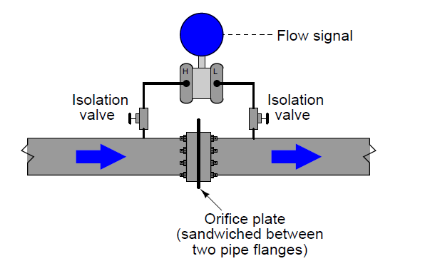
Inferring gas and Liquid Flow – DP transmitters are widely used in measurement of fluid flow. Pressure dropped across a constriction in the pipe varies in relation to flow rate (Q) and fluid density (ρ). So long as fluid density remains fairly constant, we may measure pressure drop across a piping constriction and use that measurement to infer flow rate. The most common form of constriction is the orifice plate. This is a metal plate with a precisely machined hole in the center. As fluid passes this hole, its velocity changes, causing a pressure drop to form.
Differential Pressure Transmitter Industrial Applications

Since both ports of the transmitter connect to the same process line, static fluid pressure within that line has no effect on the measurement. Only differences of pressure between the upstream and downstream sides of the constriction (orifice plate) cause the transmitter to register flow.
Don't miss out on key updates, join our newsletter list here.

Tuesday, November 6, 2018

How to Wire a 4-20 mA Current Loop

A 4-20 mA current loop is a series of connected elements like flashlight batteries. The elements of a current loop are connected in series. An easy way to remember the connections is (+)  (-), (-)  (+), then reverse the power supply connections (+) (+), (-) (-).
Wiring a 4-20 mA current loop

When we redraw the above circuit, we get to know how to wire into a junction box as shown below:
Wiring a 4-20 mA current loop

To add a PLC or computer input, we just insert into the loop. Always remember the (+)  (-), (-)(+) except at the power supply.
Adding a computer or PLC input, the wiring will look as follows:
Wiring a 4-20 mA current loop

Please note that you can only make one ground in a 4-20 mA system. Multiple grounds will cause erroneous readings.
Important items that must be checked when determining loop compliance or Power supply voltage:
  • The compliance voltage must be great enough to fully power all the loop devices at 20 mA. It is usually better to assume 25 mA max to allow yourself some ''head room''. You must also have enough voltage available to account for the drop in the wires. 
  • The loop power supply voltage must not exceed the maximum voltage rating of any device in the loop e.g. the transmitter above the maximum loop voltage of 30 VDC. Be aware of safety. If you are using low voltage wiring, you generally want to keep the voltage below 28 VDC. 
  • Note that, to calculate the required loop power supply (for compliance purpose), you add  up the voltage drops around the loop at the highest expected current. Loop powered devices (like the transmitter and meter above), will tell you the required voltage in their data sheets. 
Don't miss out on key updates, join our newsletter list here.

Wednesday, October 24, 2018

Instrumentation and Control Symbols

Here we look at common instrument symbols used in various types of technical diagrams that are used to document instrument systems.

Instrument Bubbles
Instrument Bubbles

Line Types
Instrumentation Line types Symbols

Note that, the single backlash signifying discrete or binary type has been removed from ISA standard. Regular Pneumatic and Electrical Line Symbols may represent either continuous or discrete states. 

Process/Instrument Line Connections
Process/Instrument line connections


Process Valve Types
Process Valve Types


Valve Actuator Types

Valve Failure Mode
Valve Failure Mode
Liquid Level Measurement Devices
Liquid level measurement devices

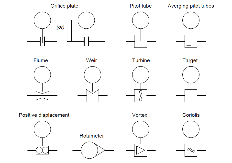
Flow Measurement Devices  (Flowing from left to right)
Flow Measurement devices
Flow Measurement Devices

Process Equipment Symbols

Functional Diagrams Symbols
Functional Diagrams symbols

Single-line electrical diagram
single line electrical diagrams
Single-line electrical diagram

Fluid Power Diagram Symbols
You can also read: 

Don't miss out on key updates, join our newsletter list here.