One of the most common and useful pressure
measuring instrument used in most industrial measurement applications is the
differential Pressure transmitter. This device senses the difference in
pressure between two ports and outputs a signal representing that pressure in
relation to a calibrated range.
Differential Pressure transmitters constructed for
industrial measurement applications typically consists of a strong (forged
metal) body housing the sensing element(s), topped by a compartment housing the
mechanical and/or electronic components necessary to translate the sensed
pressure to a standard instrumentation signal e.g. 3-15 PSI, 4-20 mA, Digital
Fieldbus codes as shown in the below Diagrams:
In the below example of Rosemount differential
pressure transmitter, the pressure-sensing element is housed in the bottom half
of the device (forged-steel structure) while the electronics are housed in the
top half (the coloured, round, cast-aluminium structure)
Every differential Pressure (DP, d/p or ∆P)
transmitter has two pressure ports to sense different process fluid pressures.
These ports typically have ¼ inch female NPT threads to readily accept
connections to the process. One of these ports is labelled “high” and the other
is labelled “low’’. This labeling does not necessarily mean that the “high”
port must always be at a greater pressure than the “low’’ port. What these
labels represent is the effect any increasing fluid Pressure applied to that
port will have on the direction of the output signal’s change. Note that, a
differential pressure instrument responds only to differential pressure while
ignoring the common-mode pressure (gauge pressure common to both ports).
The most common sensing element used by modern DP
transmitters is the diaphragm. One side of this diaphragm receives process
fluid pressure from the “high’’ port while the other receives process fluid
pressure from the “low’’ port. Any difference of pressure between the two ports
causes the diaphragm to flex from its normal resting (center) position. This
flexing is then translated into an output signal by any number of different
technologies depending on the manufacturer and the transmitter model.
Differential Pressure (DP)
Transmitter Applications
The combination of two differential pressure ports
makes the DP transmitter very versatile as a pressure-measuring device. This
one instrument can be used to measure pressure differences, positive (gauge)
pressures, negative (vacuum), and even absolute pressures, just by connecting
the “high” and “low” sensing ports differently.
In every DP transmitter application, there must be
some means of connecting the transmitter’s pressure-sensing ports to the points
in a process. Metal or plastic tubes (or pipes) work well for this purpose, and
are commonly called impulse lines or gauge lines or sensing
lines. Typically these tubes are connected to the transmitter and to
the process by means of compression fittings which allow for relatively easy
disconnection and re-connection of tubes.
Key applications of DP transmitters
include:
Measuring Process Vessel Clogging
– We may use the DP transmitter to
measure an actual difference pressure across a process vessel such as a filter,
a heat exchanger, or a chemical reactor. The diagram below shows the use of a
DP transmitter to measure clogging of a water filter:
From the diagram above, you can see the high side
of the DP transmitter connects to the upstream side of the filter and the low
side of the transmitter to the down side of the filter. This way, increased
filter clogging will result in an increased transmitter output. Since the
transmitter’s internal pressure-sensing diaphragm only responds to differences
in pressure between “high” and “low” ports, the pressure in the filter and pipe
relative to the atmosphere is completely irrelevant to the transmitter’s output
signal. The filter could be operating at a line pressure of 15 PSI or 15000 PSI
– the only variable the DP transmitter measures is the pressure drop across the
filter. If the upstream side is 15 PSI and the downstream side is 14 PSI, the
differential pressure will be 1 PSI sometimes labelled PSID, where “D” is
differential. If the upstream pressure is 15000 PSI and the downstream pressure
is 14,999 PSI, the DP transmitter will still see a differential pressure of
just 1 PSID.
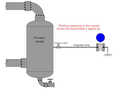
Measuring positive gauge pressure
– DP instruments can also serve as
gauge pressure instruments. If we simply connect the “high” side of a DP
instrument to a process vessel using an impulse tube, while leaving the “low”
side vented to atmosphere, the instrument will interpret any positive pressure
in the vessel as a positive difference between the vessel and the atmosphere.
Most DP instrument manufacturers offer gauge
pressure versions of their differential instruments with “high” side port open
for connection to an impulse line and the “low’’ side of the sensing element
capped off with a special vented flange, effectively performing the same
function as in the above figure.
Measuring absolute Pressure – Absolute pressure is defined as the difference
between a given fluid pressure and a perfect vacuum. We may build an absolute
pressure sensing instrument by taking a DP transmitter and sealing the “low”
side of its pressure-sensing element in connection to a vacuum chamber as shown below. This
way, any pressure greater than a perfect vacuum will register as a positive
difference.
Measuring Vacuum – The same principle of connecting one port of a DP
device to a process and venting the other works as well as a means of
measuring vacuum (Pressure below that of atmosphere). All we need
to do is connect the “low” side to the vacuum process and vent the ‘’high” side
to the atmosphere as shown below:
Any pressure in the process less than atmospheric
will register to the DP transmitter as a positive difference (with P-high greater
than P-Low ). Thus the stronger the vacuum in the process
vessel, the greater the signal output by the transmitter.
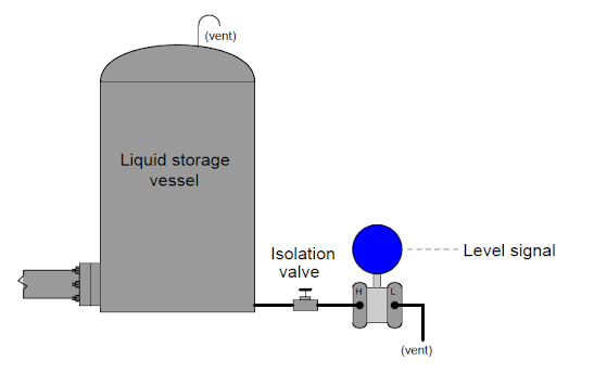
Inferring liquid level – Liquids generate pressure proportional to height
(depth) due to their weight. The pressure generated by a vertical column of
liquid is proportional to the column height (h), and liquid’s mass density (ρ),
and the acceleration of gravity (ɡ):
P=ρɡh
As the liquid in the vessel increases, the amount
of hydrostatic pressure applied to the transmitter’s ‘’high’’ port increases in
direct proportion. The width of the vessel is irrelevant to the amount of
pressure produced only the liquid height (h), density (ρ), and gravity (ɡ) are significant. Thus the transmitter’s increasing signal represents the
height of liquid inside the vessel no matter the size or shape of the vessel.
h = P/ρɡ
You can also read: Advantages and Disadvantages of Pneumatic Instruments
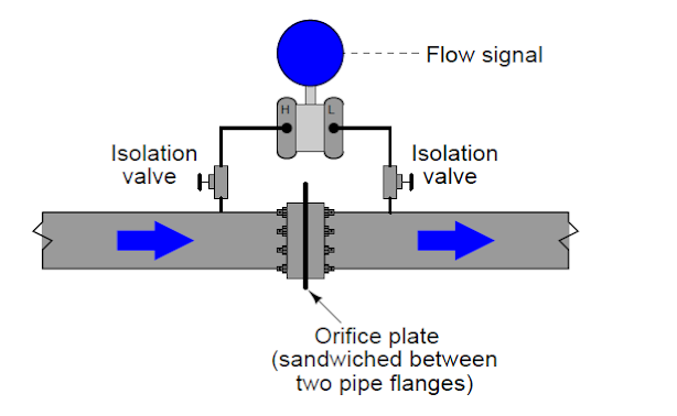
Inferring gas and Liquid Flow – DP transmitters are widely used in measurement of
fluid flow. Pressure dropped across a constriction in the pipe varies in
relation to flow rate (Q) and fluid density (ρ). So long as fluid density
remains fairly constant, we may measure pressure drop across a piping
constriction and use that measurement to infer flow rate. The most common form
of constriction is the orifice plate. This is a metal plate with a precisely
machined hole in the center. As fluid passes this hole, its velocity changes,
causing a pressure drop to form.
Since both ports of the transmitter connect to the
same process line, static fluid pressure within that line has no effect on the
measurement. Only differences of pressure between the upstream and downstream
sides of the constriction (orifice plate) cause the transmitter to register
flow.
Don't miss out on key updates, join our newsletter list here.


Thank you sir
ReplyDeleteA good summary and presentation of how a DP transmitter are being used and connected to a process, understanding these things are a big help when performing a DP transmitter calibration.
ReplyDelete