Showing posts with label Automation. Show all posts

Thursday, December 13, 2018

Types of Proximity Sensors used in Industrial Control

Almost every automated manufacturing operation has sensors that ensure that the system is working correctly.
Examples of Sensors that are used in industrial control are:
Non-Contact Presence Sensors (Proximity Sensors)
Contact sensors are often avoided in automated systems because wherever parts touch there is wear and a potential for eventual failure of the sensor. Automated systems are increasingly being designed with non-contact sensors. The three most common types of non-contact sensors in use today are:
  • Inductive proximity sensor
  • Capacitive proximity sensor
  • Optical proximity sensor

The above sensors are actually transducers, but they include control circuitry that allows them to be used as switches. The circuitry changes an internal switch when the transducer output reaches a certain value.
Hall Effect Limit Switches
Hall Effect Limit Switch

The inductive Sensor
This is the most widely used non-contact sensor due to its small size, robustness, and low-cost. This type of sensor can only detect the presence of electrically conductive materials.
The DC power supplied is used to generate AC in an internal coil, which in turn causes an alternating magnetic field. If no conductive materials are near the face of the sensor, the only impedance to the internal AC is due to the inductance of the coil. If however, a conductive material enters the changing magnetic field, eddy currents are generated in that conductive material, and there is a resultant increase in the impedance to the AC in the proximity sensor. A current sensor, also built into the proximity sensor detects when there is a drop in the internal AC current due to increased impedance. The current controls a switch providing the output.

Inductive Sensor
Inductive Sensor

 
Capacitive proximity Sensors
These sensors sense the target objects due to the target’s ability to be electrically charged. This works both on conductors and non-conductors.
Inside the sensor is a circuit that uses the supplied DC power to generate AC, to measure the current in the internal AC circuit, and to switch the output circuit when the amount of AC current changes. Unlike the inductive sensor, the AC does not drive a coil, but instead tries to charge a capacitor. The AC can move current into and out of this plate only if there is another plate nearby that can hold the opposite charge. The target being sensed acts as the other plate.
Capacitive Proximity Sensor

If this object is near enough to the face of the capacitive sensor to be affected by the charge in the sensor’s internal capacitor plate, it will respond by becoming oppositely charged near the sensor, and the sensor will then be able to move significant into and out of its internal plate.
Optical Proximity Sensors
These are widely used in automated systems because they have been available longer and some can fit into small locations. They are commonly known as light beam sensors of the thru-beam type or of the retro-reflective type. A complete optical proximity sensor includes a light source, and a sensor that detects the light. The light source is supplied because it is usually critical that the light be tailored for the light sensor system. The light source generates a light of a particular frequency which is able to be detected by the light sensor in use. Infra-red light is used in most optical sensors. To make the light sensing system more foolproof, most optical proximity sensor light sources pulse the infra-red light on and off at a fixed frequency. The light sensor circuit is designed so that light that is not pulsing at this frequency is rejected.
Optical Sensors
Optical Proximity Sensors

The light sensor is a semiconductor device such as a photo diode which generates a small current when light energy strikes it or more commonly a photo transistor or a photodarlington that allows current to flow if light strikes it.
Some of the manufacturers of proximity sensors include:

Don't miss out on our updates, join our newsletter list here.

Monday, December 10, 2018

Programmable Logic Controllers (PLC)

Programmable logic controllers (PLC) play an important role in automation sector. Various industries like Food & Beverage, Chemical, Petrochemical, Power generation etc.  use PLC.
We have several types of PLC designs:
Compact PLC: This is built by several modules within a single case. The I/O capabilities are decided by the manufacturer and not the user.
Modular PLC: This is built with several components that are plugged into a common rack or bus with extended I/O capabilities. It contains power supply module, CPU and other I/O modules that are plugged together in the same rack, which are from the same manufacturers or from different manufacturers.
Soft PLC: This is an advanced PLC system that consists of compact, rack mounted components such as power supplies, I/O modules and a CPU which embeds a powerful PLC Control software.
Programming Languages of PLC
There are several programming languages used to write programs in a PLC. They include but not limited:
  • Ladder Diagram
  • Instruction List
  • Functional Block Diagram
  • Sequential Function Chart
  • Structured Text

So what are some of the components that make up a Programmable Logic Controllers?
Components that make up a PLC system
PLC  System

Functions of each component:


CPU – This the unit that contains microprocessors
Input and Output Sections – This is where the processor receives information from external devices and communicates information to external devices.
Power Supply Unit– It converts the Main AC voltage to low DC voltage.
Programming device – Used to enter the required program into the memory of the processor.
Memory Unit – This is where the program is stored that is used to control actions.
The Operation of a PLC
Check the input status: First the PLC takes a look at each I/O to determine if it is on or off.
Execute Program: Next the PLC executes the program one instruction at a time. 
Update output status: Finally the PLC updates the outputs. It updates the outputs based on which inputs were on during the first step. 
 
How a PLC system works
The Working of a PLC system

Advantages of PLC:
  • More flexibility
  • Lower cost
  • Increased reliability
  • Faster response
  • Easier to troubleshoot
  • Communication capability
  • Remote control capability

Disadvantages:
  • They can render some jobs redundant
  • They have a high initial cost
  • If a Programmable logic controller stops, then the production stops 

Industrial Applications of PLCs
  • Food and Beverage industry
  • Gas and Water Filling Stations
  • Power Sector
  • Bottling Plants

Some of the Top PLC Brands in the world include:
Don't miss out on our Control and Automation articles, join our Newsletter list here.

Friday, December 7, 2018

How to upgrade your Legacy Equipment for industry 4.0

Scholar and leadership expert Warren Bennis once said, “In life, change is inevitable. In business, change is vital.” This wisdom resonates with every business owner, but none more than the manufacturer.
We are in the midst of a new industrial revolution, one which will significantly impact the manufacturing industry. Experts are calling it Industry 4.0, the fourth wave in the industrial revolution behind steam power, electricity and computing.
According to TechRadar, Industry 4.0 is “the label given to the gradual combination of traditional manufacturing and industrial practices with the increasingly technological world around us.” Industry 4.0 is ushering in a new era of production where automation and data exchange are integrated into the manufacturing process to streamline productivity.
Sounds great, right? It is, if you can upgrade your legacy equipment. Nobody enjoys the process of upgrading, let alone talking about it, but this is a revolution you don’t want to miss. Here’s how you can upgrade your legacy equipment to successfully ride the wave of Industry 4.0. 
Industrial Internet of Things
The Industrial Internet of Things (IIoT) is the interconnection between manufacturing and production equipment. This equipment uses sensors and internet connectivity to communicate with themselves and one another to create a more efficient production output. As a result, equipment can consider factors like stress on the electrical grid and projected weather to determine the most efficient way to operate at any given time.
According to Gartner, a leading research and advisory company, more than half of major new business processes and systems will incorporate some element of the IIoT by 2020. What’s more, McKinsey Global Institute reported that in the last five years, the number of connected machines has grown by 300 percent.
These businesses are onto something; there are many benefits of integrating the IIoT into manufacturing processes. Information gleaned from the IIoT provides access to real-time data and insights on equipment’s performance and use. Operators can also closely track the lifespan of their machinery in order to proactively plan for maintenance and upgrades. IIoT integration also aids in the automation process. Digitally connecting the machinery creates a mesh that seamlessly translates into full automation. Finally, clients can more readily track the progress of their order with insights provided by the IIoT.
Integrating the IIoT with existing equipment can be challenging, but it isn’t impossible. Most legacy equipment can be retrofitted with sensors and other online monitoring devices.
Smart Factories
In the past, many manufacturing facilities relied on Manufacturing Operations Management (MOM) software to integrate the many independent facets of the production process. Unfortunately, this technology is not able to manage production processes in real-time.
Smart Factory software integrates every part of the production process, including production, resources, supply chain, maintenance and human resources, in order to create a single, efficient output.
This technology enables factory managers to examine data once unavailable, informing decisions about production and other business processes. With Smart software, operators can be more responsive to several factors, including resource availability and cost, consumer demand, market fluctuations, and more. 
Wireless HART network
An Example of Wireless HART mesh network

Digital Supply Chains
Digital supply chains aren’t simple A to B, B to C, C to D processes. In these systems, relationships between different parts of the overall production process are affected by changes or events elsewhere in the system and able to adapt to those changes.
To create a truly digital supply chain, the facility must consider all factors that could potentially impact each part of the supply chain, all the while remedying any issues that may impede the supply chain from operating as designed. Insights from a digital supply chain give manufacturers a real-time overview of every link in the supply chain. As a result, they can quickly respond to problems and simulate scenarios to proactively plan for the future.
To do this well, factories must integrate every step of the product life cycle. This includes everything from sourcing and shipping raw materials, to ordering packaging, advertising the product, and scheduling employees on the factory floor. The digital supply chain system acknowledges that creating a product isn’t black and white. It is a highly sophisticated process that involves many interconnected variables.
Industry 4.0 is here to stay. Upgrades can cause growing pains, but in the end, change is almost always a good thing. Be a part of the next industrial revolution. Integrate your equipment and transform your business.
About the Author:
Page Long is the Marketing Operations Director at PDF Electric & Supply, which is based out of Cary, NC. PDF Electric & Supply is an automation supplier specializing in Legacy GE PLCs.
Don't miss out on our updates on Industrial automation and Control, join our newsletter list here.

Friday, November 23, 2018

Key differences between PLC and DCS systems

We have so many people with questions as to what are the similarities and differences if any between PLC and DCS systems. We will try to describe the working of these two systems and in the process help you understand the functions of each system.
Initially DCS was focused only on process control with analog signals that were used as main control system in process industries like Refining, Chemicals, and Petrochemicals etc. while PLC was focused on discrete automation with discrete on-off signals, that were used for example in Factory assembly lines and bottle lines but today DCS supports discrete I/O and some logic functions and PLCs support analog I/O with some control functions. In some instances Both PLC and DCS are used in the same plant i.e. PLCs are used on separate units on a plant floor which are then integrated with main plant-wide DCS for Control and Monitoring.
Let us now look at each system separately to help us understand more how they work.
PLC
Programmable Logic Controllers (PLCs) comes in different sizes which means various I/O and program capacities. Smallest sized PLCs are typically referred to as nano PLCs, micro PLCs and mini PLCs. They have fixed I/O and mainly used in stand-alone applications.
Large PLC support redundancy for CPU, power supply and possibly the control network, but typically not for I/O cards though there are large PLCs that support I/O redundancy by using duplicate I/O-subsystems with separate backplanes where the field instruments are wired in parallel to both I/O subsystems. The control network is typically a standard industrial Ethernet application protocol over Ethernet media and IP. The Field cabling comes directly onto the I/O card.
PLC usually support very fast scan times as required in discrete manufacturing but PID loops add to the CPU load, much more than discrete load thus making the scan time slower.
Loops are not handled individually in a PLC. Addition or change to loop requires a download of the entire program which affects other loops in the CPU as well.
PLCs are built around a given native protocol, this maybe: PROFIBUS, Modbus, DeviceNet etc. The PLC comes with its own native interface cards for native protocol supported by the PLC maker but relies on third-party interface cards for other Fieldbus protocols. The engineering software therefore automatically configures the communication interface card for the native protocol.
Key Points to note on PLC
PLCs were designed to eliminate assembly-line relays during model changeovers. PLC is easier to change than relay panels; this has reduced the installation and operational cost of the control system compared with electromechanical relay systems.

A basic block diagram of PLC system
BLOCK DIAGRAM OF A PLC SYSTEM

PLC offers the following advantages:
  • Ease of programming and reprogramming in the plant
  • Programming language is based on relay wiring symbols familiar to most plant electrical and instrumentation personnel
  • High Reliability and minimal maintenance
  • Small physical size
  • Ability to communicate with computer systems in the plant
  • Moderate to low initial investment cost
  • Available in modular designs
DCS
Distributed Control System (DCS) supports redundancy for controllers, power supply and control network as well as redundant I/O cards including fieldbus interface cards in the same backplane. The control network supports peer-to-peer communication between controllers. The control network is typically a proprietary application protocol over Ethernet media and IP. The field cabling in DCS lands on a Field Terminal Assembly (FTA) where a special system cable with a connector takes the signals to the I/O card.
Loops in a DCS are executed individually. The scan time in a DCS is set individually for each loop. Most loops run at 1000ms although 250ms is common for pressure and flow loops in refining and petrochemicals and even 100ms is also possible. The scan time is constant, and does not change with task loading. This is important for PID control and time-based functions such as integration/totalizing and lead-lag dynamic compensation.
Loops in a DCS are managed individually. A change and download to one loop doesn’t affect the other loops.
A DCS has an integrated development environment where I/O control strategy and operator graphics are created together and stored in a single database. This means once a tag is created in the DCS it automatically becomes available everywhere in the system with the same human readable tag name for use in basic control, advanced control, graphics, faceplates, trending, alarming, and turning etc.  Without mapping data through registers or other tag names makes it easy to do changes or additions.
The Sensor & Actuator level “H1” Fieldbus network supported by DCS is basically FOUNDATION fieldbus for instrumentation and PROFIBUS-DP for motor controls.
The DCS comes with its own native Fieldbus interface cards. The engineering software therefore automatically configures the communication interface cards for the variables used in the control strategy and graphics.
Key Points to Note on DCS
DCS is miniaturized version of the multitasking, multivariable, multi-loop controller used for process control. It is functionally and geographically processing distributed system. Equipment making up a DCS is separated by function and is installed in two different work areas of a processing installation. Equipment for operator to monitor process condition and to manipulate the set point of the process operation is located in a central control room; from where the operator can view information transmitted from the process area and displayed on a video display unit and can change control condition from a keyboard. DCS systems are suitable for the following processes:

  • Where a single centralized system is not adequate i.e. Power, Steel, Pulp & Paper plants, Fertilizer etc.
  • Processes of different level of hierarchy
  • Processes which can be divided into different and functionally independent sections, based on functional scope and geographical distribution
DCS offers the following Advantages:
  • Compact to contain ON/OFF controllers
  • Reduced complexity and easy expandability
  • High Speed of the control processing
  • Control Algorithms changes do not call for hardware changes
  • Continuous trend data is available
  • User friendly but higher data security
  • Plant data are transparent on the network
  • Sequential, batching and feedback control are possible
Don't miss out on key updates, join our newsletter list here.
Differences between PLC and DCS based Systems
                PLC
           DCS
Redundancy not possible or limited
Redundancy possible at every level
It is used for low loop count
It is used for any loop count
Performance drops with increasing loop count
No change in performance with increasing loop count
Purely free running mode
Highly efficient multitasking mode
Analog processing simulated through digital computer
Analog processing done in real frequency domain function
No interplant connectivity
Fully Functional Inter-plant connectivity
Individual database for every node
System-wide global database
Typical performance: 100 PID loops/sec
Typical Performance: More than 1000 PID loops/sec.

Do you have comments or questions on PLC or DCS? Feel free to post them in the comments section below. 


Monday, November 19, 2018

Components in a Controlled Automation System

Essential components in any controlled automation system include:
  • The actuator (which does the work)
  • The controller (which ”tells” the actuator to do the work)
  • The sensor (which provides the feedback to the controller so that it knows the actuator is doing work)

An example of a simple controlled automation system is shown below:
Controlled Automation System

A controlled system may either be analog controlled system or digital controlled system. Let's consider the following analog controlled system:
Controlled Automation System

The actuator is a hydraulic servovalve and a fluid motor. The servovalve opens proportionally with the voltage it receives from the controller and the fluid motor rotates faster if it receives more hydraulic fluid. There is a speed sensor connected to the motor shaft, which outputs a voltage signal proportional to the shaft speed. The controller is programmed to move the output shaft at a given speed until a load is at given position. When the program requires the move to take place, the controller outputs an approximately correct voltage to the servovalve, then monitors the sensor’s feedback signal. If the speed sensor’s output is different from expected i.e. indicating wrong motor speed, the controller increases or decreases the voltage supplied to the servovalve until the correct feedback is achieved. The motor speed is controlled until the move finishes. As with any other control system, the program may include a function to notify a human operator if speed control isn’t working.
Having looked at analog controlled system above, let's now consider an example of a digital controlled system:
Controlled Automation System

The above figure represents a simple digital controlled system in which the actuator consists of a pneumatic valve and a pneumatic cylinder that must be either fully extended or retracted. The controller is a PLC that has been programmed to extend the cylinder during some more complicated process and to go on to the next step in the process only after the cylinder extends. When it is time to extend the cylinder, the PLC supplies voltage to the valve, which should open to provide air to the cylinder, which then extend. If all goes well, after a short time the PLC will receive a change in voltage level from the limit switch, allowing it to execute the next step in the process. If the voltage from the switch does not change for any reason ( faulty valve or cylinder or switch, break in a wire, obstruction preventing full cylinder extension etc.), the PLC will not execute the next step. The PLC may even be programmed to turn on a “fault” light when such a delay occurs.

Don't miss out on our Industrial Instrumentation & Automation updates, join our Newsletter list here.

Sunday, November 18, 2018

Key Features and Applications of Remote Terminal Units (RTU)

Remote Terminal Units also called Remote Telemetry Units or Remote Telecontrol Units are Microprocessor controlled devices that interfaces in the physical world to either SCADA (Supervisory Control and Data acquisition) system or DCS (Distributed and Control system).  They transmit data to a master system and uses messages from the master supervisory system to control objects connected to the system.
They are designed for use in applications in remote locations unattended. These locations may have limited to no power, hence RTUs are designed to consume low power than DCS and PLC & this enables operation on solar power and batteries.
In application where supervision is done from distant central location, the SCADA software sits in the central office connected over a backhaul network typically using radio communication to the RTUs located far away and in most cases geographically spread out. The communication may be interrupted for long periods of time therefore RTUs have on-board  data storage continuing local data collection for more than a month if backhaul communication is lost as well as “history backfill’’ uploading this data once the connection is established again. Report by exception communication mechanisms are often used to minimize backhaul communication using Wide Area Networks e.g. Mobile, Microwave, Satellite.
RTU in Multidrop Communication System

Remote Terminal Units (RTU) Configuration
The RTU configuration software is separate from the HMI (Human Machine Interface) software from a third-party manufacturer i.e. two separate databases. RTU is configured first; next the OPC server is configured. For a native OPC server this happens automatically, but for OPC server from a third-party, manual data mapping is required which can be time-consuming and error prone requiring thorough testing. In most cases native OPC server is preferred. To finalize, the HMI database has to be configured for graphics, alarms, and trends etc.
The 4-20 mA AI and AO cards for a RTU optionally support native HART pass through hence separate HART multiplexer (MUX) hardware and associated work is not required. Native HART pass through AI and AO cards are much easier to integrate and should be specified if 4-20 mA is used. Since RTUs are generally used in very slow monitoring applications that don’t require fast control, some applications do not use the real-time analog 4-20 mA but only the digital HART communication multi-drop topology. This means the field instruments draw less than 4 mA instead of up to 20 mA hence further reducing the overall power consumption.
Applications of Remote Terminal Units (RTU)
Remote terminal units are commonly used in the following applications:
  • Electrical Power Transmission Networks and Associated Equipment.
  • Remote Monitoring of Functions and the whole Instrumentation Network in Oil and Gas (offshore platforms, onshore oil wells, Pump Stations on Pipelines)
  • Water and Wastewater collection and supply networks including the Pumping stations.
Don't miss our on our Industrial Instrumentation updates, join our Newsletter list here.

Tuesday, September 25, 2018

Electrical Power Distribution Automation

Electrical power distribution is the last stage in the delivery of electric power. It carries electricity from the transmission system to the individual consumers. The primary distribution lines carry this medium voltage to distribution transformers.


The distribution networks of concern in this stage are 11KV lines or feeders downstream of the 33KV substations. Each 11KV feeder, which come from the 33KV substation branches further into several subsidiary 11KV feeders to carry power close to the load points, where it is further stepped down to either 230V or 414V.

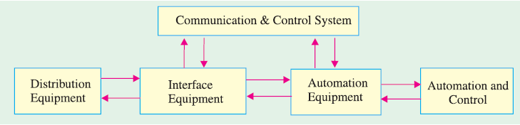
Electrical Power Distribution Automation

Normally for fault detection, we have circuit breakers i.e. one circuit breaker for every main 11KV feeder at the 33KV substations, but these circuit breakers are provided as a means of protection to completely isolate the downstream network in the event of a fault. For quick fault detection, isolation of faulty region and restoration of supply to the maximum outage area, we need to have a system that can achieve a finer resolution.

In the event of a fault on any feeder section downstream, the circuit breaker at the 33KV substation trips, as a result, we have a blackout over a large section of the distribution network. If we can precisely identify the faulty segment, we can reduce the blackout area, by re-routing the power to the healthy feeder segments through the operation of sectionalizing switches, placed at strategic locations in various feeder segments.

The lack of information at the 33KV substations of the loading and health status of 11KV/415V distribution transformers and associated feeders is one of the main causes of inefficient power distribution.  When we have no monitoring, overloading occurs, which results in low voltage at the customer end, and this increases the risk of frequent breakdowns of the transformers and feeders.
To prevent the above problems from occurring in a power distribution network, we need to have an automated electrical power distribution system.


How Electrical Power Distribution Automated System work

To enhance the electrical power distribution reliability, sectionalizing switches are provided along the way of primary feeders. Thus, by adding fault detecting relays to the sectionalizing switches along with circuit breaker and protective relays at the distribution substations, the system is capable of determining fault sections. To reduce the service disruption area in the case of power failure, normally open (NO) sectionalizing switches called as route switches are used for supply restoration process. The operation of these switches is controlled from the control center through the Remote Terminal Units (RTU).

In a power distribution automation system, the various quantities e.g. current, voltage, switch status, temperature and oil level are recorded in the field at the distribution transformers and feeders, using a data acquisition device called Remote Terminal Unit. These quantities re transmitted on-line to the base station through a communication media. The acquired data is processed at the base station for display at multiple computers through a Graphic user interface (GUI).

In the event of a system quantity crossing a pre-defined threshold, an alarm is generated for operator intervention. Any control action, for opening or closing of the switch or circuit breaker is initiated by the operator and transmitted from the 33KV base stations through the communication channel to the remote terminal unit associated with the corresponding switch or CB. The desired switching takes place and the action is confirmed by the operator.

All these distribution automation functions of data collection, data transmission, data monitoring, data processing, man-machine interface etc. are realized using an integrated distribution SCADA (Supervisory Control and Data Acquisition) system.

Don't miss out on key updates, join our newsletter list here.

The implementation of SCADA system in any electric utility involves the installation of the following units:
  • Sectionalizing Switches
  • Remote Terminal Units
  • Data Acquisition System
  • Communication Interface
  • Control PC