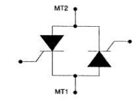
The Triac is a three-terminal device that is
similar to the SCR except that the Triacs can conduct
current in both directions. Its primary use is to control power to AC loads
such as turning AC motors on and off or varying the power for lighting and
heating systems. The Triac is a solid state device that acts like two SCRs that
have been connected in parallel with each other (inversely) so that one SCR
will conduct the positive half-cycle and the other will conduct the negative
half-cycle. Before the triac was designed as a single component, two SCRs were
actually used for this purpose.
The figure 1 below shows the symbol for the triac,
and its pn Structure. The terminals of the triac are identified as main
terminal 1 (MT1), main terminal 2 (MT2), and gate. The multiple pn structure is
actually a combination of two four-layer (pnpn) junctions.
 |
| Figure 1 |
As the name suggests, the load current passes
through the main terminals, and the gate controls the flow. Figure 2 below
shows the equivalent circuit of the triac, which consists of two back-to-back
SCRs with a common gate.
The operation of the triac can be explained by the
two-SCR model in Figure 2. From the figure, you can see the SCRs are
connected in an inverse parallel configuration. One of the SCRs will conduct
positive voltage and the other will conduct negative voltage.
When MT2 is more positive, the current flows
through first SCR; when MT1 is more positive the current flows through Second
SCR.
Unlike the two SCRs, the Triac is triggered by a
single gate. This prevents problems of one SCR not firing at the correct time
and overloading the other.
The operating characteristics of the Triac are best
explained using the characteristic curve shown in Figure 3:
 |
| Figure 3 |
In the figure above, you can see that the triac can
conduct both positive and negative current. The Voltage is shown along the
horizontal x-axis, and current is shown along the vertical y-axis. This diagram
also shows a second graph with four quadrants. These quadrants are used to
explain the operation of the triac as polarity to its MT1 and MT2 and gate
changes.
Notice that the right half of the graph (in
quadrant 1) looks just like the SCR curve; no current flows until either the
break over voltage is reached or the gate is triggered (indicated by dashed
line).
This same pattern is repeated in quadrant 3 (for
voltage and current of the opposite direction). Also, like the SCR, once the
triac is triggered on, it will remain on by itself until the load current drops
below the holding current value (IH)
A Single cycle of AC has a positive and a negative
half-cycle. The triac requires a trigger pulse at the gate for each half-cycle
and works best if the trigger is positive for the positive half-cycle and
negative for the negative half-circle (Although in most cases the triac will
also trigger if the gate goes negative in the positive half-cycle and if it
goes positive in the negative half-cycle.
You can also read:
Applications of Triacs
The Triac is required in circuits where AC Voltage
and Current need to be controlled like the SCR controls dc current. Another
difference between the triac and SCR is that the Triac can be turned on either
by a positive or negative gate pulse. The gate pulse need only be momentary and
the Triac will remain in conduction until the conditions for commutation are
satisfied.
A triac can be used as an-off solid-state switch
for AC loads or to regulate power to an AC load, such as dimmer switch.
Triacs are available in various packages, some of
which can handle currents up to 50 A (which is considerably less than the SCR).
Don't miss out on key updates, join our newsletter list here.
No comments:
Post a Comment