In any measurement system, the instruments in use are prone to
errors due to aging or manufacturing tolerances. These instrument errors must
be stated before taking any measurement. Some of the common terms used when
describing the performance of an instrument are:
- Accuracy – The accuracy of an instrument is often stated as % of the range or full-scale deflection. e.g. A Pressure gauge with a range 0 to 500 kpa and an accuracy of plus or minus 2% full-scale deflection, could have an error of plus or minus 10 kpa. When the gauge is indicating 10 kpa the correct reading could be anywhere between 0 and 20 kpa and the actual error in the reading could be 100 %. When the gauge indicates 500 kpa the error could be 2 % of the indicated reading.
- Range – The range of an instrument is usually regarded as the difference between the maximum and minimum reading, e.g. a thermometer that has a scale from 20 to 100 ° C has a range of 80 °C. This is also called the Full scale deflection (f.s.d.).
- Repeatability – If an accurate signal is applied and removed repeatedly to the system and it is found that the indicated reading is different each time, the instrument has poor repeatability. This is often caused by friction or some other erratic faulty in the system.
- Stability – Instability will likely occur in instruments involving electronic processing with a high degree of amplification. Causes of this could be environmental factors such as temperature and vibration, e.g. a rise in temperature may cause a transistor to increase the flow in current which in turn makes it hotter and so the effect grows and the displayed reading DRIFTS. In extreme cases, the displayed value may jump about caused by for example a poor electrical connection affected by vibration.
- Time lag error – This occurs when an instrument takes time for a change in the input to show up on the indicated output. This time may be very small or very large depending upon the system. If the indicated output is incorrect because it has not yet responded to the change, then we have time lag error. When a signal changes a lot and quite quickly e.g. a speedometer, the person reading the dial would have a great difficulty determining the correct value as the dial may be still going up when in reality the signal is going down again.
- Drift – This occurs when the input to the system is constant but the output tends to change slowly. For example when switched on, the system may drift due to the temperature change as it warms up.
- Reliability – An instrument in most cases will have a predicted life span. The more reliable it is, the less chance it has of going wrong during its expected life span. The reliability is hence a probability ranging from zero ( it will definitely fail) to 1.0 ( it will definitely not tail).
INSTRUMENT CALIBRATION
Most instruments have a built-in mechanism for making adjustments. These are:
- The range adjustment
- The zero adjustment
In order to Calibrate an instrument an accurate gauge is required. This is likely to be a Secondary standard. Instruments calibrated as a secondary standard have themselves been calibrated against a primary standard.
Procedure
An input representing the minimum gauge setting should be applied. The output should be adjusted to be correct. Next the maximum signal is applied. The range is then adjusted to give the required output. This is repeated until the gauge is correct at the minimum and the maximum values.
You can also read:
You can also read:
Calibration Errors
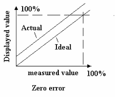
Range and zero Error – After obtaining correct zero and range for the instrument, a calibration graph should be produced. This involves plotting the indicated reading against the correct reading from the standard gauge. This should be done in about 10 steps with increasing signals and then with reducing signals. Several forms of error could show up. If zero or range is still incorrect the error will appear as shown figure 1 and 2 below: |
| Figure 1 |
 |
| Figure 2 |
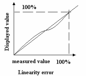
Hysteresis and Nonlinear Errors – Hysteresis is produced when the displayed values are too small for increasing signals and too large for decreasing signals. This is commonly caused in mechanical instruments by loose gears, linkages and friction. It occurs widely with equipment involving magnetization and demagnetization. The calibration may be correct at the maximum and minimum values of the range but the graph joining them may not be a straight line ( when it ought to be). This is a nonlinear error. The instrument may have some adjustments for this and it may be possible to make it correct at mid range as shown in figure 3 and 4.
 |
| Figure 3 |
 |
| Figure 4 |
Don't miss out on key updates, join our newsletter list here.
No comments:
Post a Comment