Thursday, August 15, 2019

How a VFD works and when to use it


Did you know you could save on energy consumption and costs by using a VFD? You can also tighten your processes, increase production, reduce maintenance, and extend the life of your equipment.

But what is a VFD, you ask? Let’s take a look.

Defining VFD

VFD stands for variable frequency drive. It’s a motor controller for electric motors. VFDs are also known as adjustable speed drives, adjustable frequency drives, AC drives, microdrives, inverters, and variable speed drives.

The word “frequency” in the name relates to the frequency of the power delivered to the motor, which is measured in hertz. Changing the frequency changes the speed of the motor shaft.  If your electric motor doesn’t need to run at full speed for the entire process, you can save some juice and some wear and tear by installing a VFD to vary the speed of the motor.

A variable frequency drive can also get a motor started and ramp it up to speed at a controlled acceleration rate. This makes the start-up smooth, while also saving on electricity and motor life.

A VFD allows one motor to be used for processes that may require or allow different speeds.
Variable Speed Drive in Operation
Variable Speed Drive


How Does a VFD Operate?

A VFD converts fixed frequency AC line voltage to DC, then makes new AC at whatever voltage and frequency are needed to run the motor at the desired speed. The VFD consists of a converter section, a filter section, an inverter section and control section. 
  • The Control section operates the entire VFD, monitors the VFD and motor for safe operation, and interact with the machine operator or automation control system. 
  • The Converter uses diodes and/or SCRs to change AC utility power to DC
  • The Filter ''Cleans'' the DC power with inductors and capacitors
  • The Inverter makes new AC power for the motor using transistors as switches

Those switches are what allow the VFD to function at different speeds. The transistorized switches let the VFD adjust the frequency and voltage of the power supplied to the motor. As the frequency changes, so does the motor speed.

What’s It For?

Anytime you have a system run by an AC electric motor, you may have a need for a VFD. For example, a common use is controlling the speed of a water pump. If the pump is part of a water treatment process, a low demand for water can mean that the water doesn’t exit the plant at the same speed it enters for treatment.

To slow down the supply-side, a VFD is used to slow the water pump.

As mentioned before, a VFD can be used to get a motor started and smoothly accelerate it to operating speed. Energy usage is reduced if operating speed is below full speed.  There is less strain on the motor, less wear and tear on the machinery, and it doesn't just start with a jolt. Using VFDs on conveyors and belts eliminates those jerky starts and increases throughput without damaging equipment.

VFDs can be regulated with a PLC instead of manual adjustment. It’s an easy way to automate a repetitive task and reduce labor cost.

A VFD is a handy little gadget that can help you tighten your process controls, increase production, and minimize mistakes. Your maintenance and repair needs go down, and so does your electricity bill. At the end of the shift, your company has made a little more money than it did before.
You can also read: 


Don't miss out on key updates, join our newsletter list here.
About the Author:
With over 25 years of experience in the industrial automation repair industry, Jeff Conner is the Dallas Service Manager for Control Concepts and serves on the Advisory Committee for the Electronics Technologies Department at Texas State Technical College.
Control Concepts helps design, fabricate, install, test, and program control systems. They service almost any brand of control found in automated systems and can send an experienced technician anywhere, wherever one is needed 24 hours a day, 7 days a week.

Monday, July 29, 2019

Why you should modernize your Relay Control System with a PLC

If you are still running a hard-wired relay control system, it may be time to consider modernizing with programmable logic controllers, or PLCs. PLCs have gotten smaller and more efficient over the years, and they can replace a complex relay system and provide a host of benefits.


Defining PLCs

A programmable logic controller is what it sounds like - a small, special-use computerized control device used in industrial systems. It handles sequential controls, counters, timers, and more. PLCs are more widely used than special-purpose digital computers and have found a place in industrial manufacturing and civil applications.

A PLC continuously monitors input values from sensors, operator controls, etc. and produces outputs to operate machinery based on programming.

How Does a PLC Work?

A PLC is made up of a CPU module, a power supply, and one or more I/O modules. There is no hard drive since the program is stored in internal memory.  A touch screen or other HMI (Human Machine Interface) is optional. The PLC stays inside a control panel and uncomplainingly does its job.

It performs several steps as part of a typical scan cycle:

  • Cycles the operating system and monitors time
  • Reads data from the input module and checks all input statuses
  • Executes user or application program
  • Performs all internal diagnostics and communication tasks
  • Writes data into the output module

As long as the PLC is on, it repeats the cycle until the programming or process comes to an end.
Programmable Logic Controllers


The Benefits of PLCs

One benefit has already been mentioned. A PLC is used across multiple industries and in smaller machinery. But there are other benefits as well. PLCs are:

  • Robust and durable
  • Easy to program
  • Reliable 
  • Easy to use

The I/O module doesn’t even need to be near the CPU. They can be miles apart and still operate connected by data cables. Your PLC isn’t stuck to a single cabinet or building. A PLC can have more than just digital inputs & relay outputs. Improvements over the years have given PLCs the ability to work with a wide variety of analog signals as well as Ethernet and serial communications protocols.

PLCs give your production lines flexibility that you don't get with relays. If you need to retool your line, you can easily reprogram your PLCs to handle the new process.

PLCs are found in such industries as chemical, automotive, steel, food/beverage and more.

Why you should modernize your Relay Control Systems with a PLC

As you have probably experienced, relays use a ton of electricity. They take up space, and they’re noisy and tend to fail a lot. All those electrical connections between relay & socket & interconnecting wires mean more downtime for maintenance. Mechanical relay systems fail more often than PLCs.

If all you need to do is turn an electrical motor on and off safely, a relay may be all you need. But most industrial processes today involve more than that. You need something modern and smart to make your processes energy-efficient and cost-effective.

Modern industry leverages the power of the computer revolution to improve almost every step of any process. Modernize your relay control systems with a PLC, and you'll wonder why it took you so long.

About the Author:

With over 25 years of experience in the industrial automation repair industry, Jeff Conner is the Dallas Service Manager for Control Concepts and serves on the Advisory Committee for the Electronics Technologies Department at Texas State Technical College.

Control Concepts helps design, fabricate, install, test, and program control systems. They service almost any brand of control found in automated systems and can send an experienced technician anywhere one is needed 24 hours a day, 7 days a week.
Friday, May 3, 2019

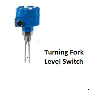
Turning Fork Level Switches

This level switch uses a metal tuning fork structure to detect the presence of a liquid or solid (powder or granules) in a vessel.
Turning Fork Level Switch
An electronic circuit continuously excites the tuning fork, causing it to mechanically vibrate. When the prongs of the fork contact anything with substantial mass, the resonant frequency of the structure dramatically decreases. The circuit detects this change and indicates the presence of material contacting the fork. The fork’s vibrating motion tends to shake off any accumulated material such that this style of level switch tends to be resistant to fouling.
You can also read: Ultrasonic Level Switches
Don't miss out on key updates, join our newsletter list here.

Tuesday, March 19, 2019

Types of Signal Converters Commonly used in Industrial Control


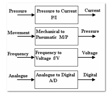
Signal converters change a signal from one form to another. In most cases, we have standard inputs and output ranges.
Types of signal converters

Most signal converters have two adjustments-zero and range.
Examples of Signal converters
Nozzle-flapper and differential pressure cells
The nozzle-flapper system is widely used in D.P. Cells. An example is shown below, that converts differential pressure (e.g. from a differential Pressure flow meter into a standard pneumatic signal). This is widely used in the control of air operated pipeline valves.
Flapper Nozzle System

The bellows respond to the differential pressure and moves the lever. This moves the flapper towards or a way from the nozzle. The air supply passes through a restrictor and leaks out of the nozzle. The output pressure hence depends on how close the flapper is to the end of the nozzle. The range of the instrument is adjusted by moving the pivot and zero position is adjusted by moving the relative position of the flapper and nozzle. This system is used in a variety of forms. Instead of bellows, a bourdon tube might be used and this is operated by an expansion type temperature sensor to produce a temperature-pneumatic signal converter.
Current/Pressure conversion 
The figures below show typical units for converting 4-20 mA into 0.2-1 bar or 3-15 psi. They contain adjustments for range and zero. They are widely used for converting the standard pneumatic and electric signals back and forth. They can also be adjusted to work with non standard inputs to convert them into a standard form.
Current to Pressure Converter (C/P)
Current to Pressure Converter

Pressure to Current Converter (P/C)
Pressure to Current Converter

Electric D.P. Cells
They provide the same functions as the pneumatic versions but they are given an output of 4-20 mA using electrical pressure transducers. They are typically used with D.P. Flow meters.
Differential Pressure Transmitter

Analogue -Digital Converters
Analogue to digital conversion is a process of turning an analogue voltage or current into a digital pattern which can read by a computer and processed, this is done by analogue -digital converters.  Lets look at the Binary Numbers, a number may be represented in digital form by simply setting a pattern of voltages on a line high or low. It is normal to use 4, 8, 16 or 32 lines. An 8 bit binary pattern is shown in the below figure:
Binary Numbers
The total pattern is called a word and the one above is an 8 bit word. The pattern may be stored in an 8 bit register. A register is a temporary store where the word may be manipulated. The Bit zero is called the least significant bit (LSB) and the bit with highest value is called the most significant bit (MSB). Each bit has a value of zero when off (LOW) or the value shown when on (HIGH). The maximum value for an 8 bit word is 255.
Digital to Analogue Converters
These are devices for converting a binary number into an analogue voltage. The change in the binary value from zero to a maximum corresponds with a change in the analogue value from 0 to maximum.
One of the manufacturers of signal converters is Omega.
Don't miss out on key updates, join our newsletter list here.

Sunday, March 10, 2019

The Inputs and Outputs of Process Measurement Instruments Commonly used in Control Systems

Basically when you are doing the troubleshooting of any instrumentation system you assume that every instrument has at least one input and at least one output and that the output(s) should accurately correspond to the input (s). In normal circumstances, if the instrument’s output is not corresponding to its input according to the instrument’s design function, then there could be something wrong with the instrument. Lets consider the inputs of the following examples of  instruments that are commonly used in process control systems:
  • Differential Pressure transmitter
  • Temperature Transmitter
  • Controller

Process measurement instruments


Controller
Each of the above instruments takes in (input) data and generates the (output) data.  In an instrumentation loop, the output of one instrument feeds into the input of the next. Such information is passed from one instrument to another.
By intercepting the data communicated between components of an instrument system, we are able to locate and isolate faults. For us to able to properly understand the intercepted data, we must understand the inputs and outputs of the respective instruments and the basic functions of those instruments. From the above diagrams, we  are able to highlight the kind of inputs and outputs for each of the instruments indicated.
To be able to check the right correspondence between the instrument inputs and outputs, we must therefore use appropriate test equipment to intercept the signals into and out of these instruments e. g. in case of analogue instruments using 4-20 mA signals we can use the electrical meters capable of measuring the current and voltage.
So what are some of the key considerations when using milliameters to measure loop current?
For you to measure the loop current, you have to break the circuit to connect the milliameter, in series with the current, and which means the current will fall to 0 mA until the meter is connected. Interrupting the current means interrupting the flow of information that is conveyed by that current, be it a process measurement or a command signal to a final control element. This can have adverse effects on the control system unless certain preparations are made before hand. The preparations can be in form of:
  • Informing the personal in charge that signal will be interrupted - state the number of times you intend to do the interruption.
  • For case, where the signal is coming from a process transmitter to a controller, the controller should be placed in manual mode, so that it will not cause an upset in the process. 
  • If the current drives process shutdown alarms, these should be disabled on temporarily basis, so that nothing shuts down upon the interruption of the signal.
  • All process alarms should be temporarily disables so that they do not cause panic.
  • If the current signal to be interrupted is a command signal from a controller to a final control element, the final control element either needs to be manually overridden so as to hold a fixed setting while the signal varies or it needs to be bypassed completely by some other devices (s)
Don't miss out on key updates, join our newsletter list here.


Thursday, February 7, 2019

Ultrasonic Level Switches


This type of level switch uses ultrasonic sound waves to detect the presence of process material either solid or liquid at one point.
The Working Principle
Sound waves pass back and forth within the gap of the probe, sent and received by piezoelectric transducers. The presence of any substance other than gas within the gap detects the received audio power, thus signalling to the electronic circuit within the bulkier portion of the device that process level has reached the detection point.
Ultrasonic Level Switches
Fig 1

Ultrasonic Level Switches
Fig 2

In Fig 1, the sound passes through the gap when filled with liquid (wet gap).
In Fig 2, the sound cannot pass through an air-filled gap (dry gap).
The lack of moving parts makes this probe quite reliable although it may be become fooled by heavy fouling.
Some of the industrial applications of Ultrasonic level  switches include:
  • Leak detection
  • As an overfill alarm
  • Detection of presence of liquids in pipeline
  • Pump Protection
  • Engine oil level control

Tuesday, February 5, 2019

The Components that make up a 4-20 mA Current Loop

The 4-20 mA current  loop is an important aspect of process measurement and control circuits. The important components that make up this loop are:
  • The Sensor
  • The Transmitter
  • The Power Source
  • The Loop itself
  • The Receiver

The following diagram shows each component with its function:
Components in a 4-20 mA current loop

This is a simple illustration of a 4-20 mA current Loop System.
 You can also read:

Don't miss out on key updates, join our newsletter list here.