Wednesday, December 13, 2023

The Fundamentals of Semiconductor Junction Thermometers

Temperature sensors can be fabricated with semiconductor processing technology by employing the temperature characteristics of the pn junction.  The batch processing and well-defined manufacturing processes associated with semiconductor technology can provide low cost and consistent quality temperature sensors.

Most semiconductor junction temperature sensors utilize a diode-connected bipolar transistor (short-circuited collector-base junction). A constant current passed through the base-emitter junction produces a junction voltage between the base and emitter (Vbe) that is a linear function of the absolute temperature. The overall forward voltage drop has a temperature coefficient of approximately 2 mV °C-1.

Bipolar transistor configured as a temperature sensor

Fig: Bipolar transistor configured as a temperature sensor

In the above figure, the base of the transistor is shorted to the collector. A constant current flowing in the remaining pn (base to emitter) junction produces a forward voltage drop VF proportional to temperature.

The temperature coefficient of a semiconductor sensor is larger but still quite small when compared to a thermocouple or resistive temperature device/detector (RTD). Furthermore, the semiconductor sensor’s forward voltage has an offset that varies significantly from unit to unit. Nonetheless, the semiconductor junction voltage versus temperature is much more linear than that of a thermocouple or RTD. Also, the temperature-sensing element, circuitry is easily integrated to produce a monolithic temperature sensor with an output that can be easily interfaced to a microcontroller and to provide features that are useful in particular applications. For instance, by using an embedded temperature sensor with additional circuitry, protection features can be added to integrated circuits (ICs). A temperature sensor becomes an embedded item in a semiconductor product when it has a secondary or supplemental purpose instead of the primary function.

Sunday, May 21, 2023

Flowmeter Calibration Methods for Liquids

 The major principles employed for liquid flowmeter calibration are:

  • In-situ calibration methods {Insertion-point velocity and Dilution gauging/tracer technique}
  • Laboratory methods {master meter, volumetric gravimetric and pipe prover}

In-situ calibration methods

Insertion-point velocity – this is one of the simplest methods of in-situ flowmeter calibration. It utilizes point-velocity measuring devices where the calibration device selected is positioned in the flow stream adjacent to the flowmeter being calibrated, such that the mean flow velocity can be measured. In difficult situations a flow traverse can be carried out to establish the flow profile and mean flow velocity.

Dilution gauging/Tracer method – this method can be applied to closed-pipe and open-channel flowmeter calibration. An appropriate tracer (chemical or radioactive) is injected at an accurately measured constant rate and samples are taken from the flow stream at a point downstream of the injection point where complete mixing of the injected tracer will have taken place. By measuring the tracer concentration in the samples the tracer dilution can be determined and from this dilution and the injection rate the volumetric flow can be calculated.

Dilution gauging by tracer injection

                                    Figure 1.0 Dilution gauging by tracer injection

Alternatively a pulse of tracer material may be added to the flow stream and the time taken for the tracer to travel a known distance and reach a maximum concentration is a measure of the flow velocity.

Related: Instruments Errors and Calibration

Laboratory calibration methods

Master meter – for this method a meter of known accuracy is used as a calibration standard. The meter to be calibrated and the master meter are connected in series and are then subjected to the same flow regime. Note that, to ensure consistent accurate calibration the master meter itself must be subject to periodic calibration.

Volumetric method – in this technique, the flow of liquid through the meter being calibrated is diverted into a tank of known volume. When full, this known volume can be compared with integrated quantity registered by the flowmeter being calibrated.

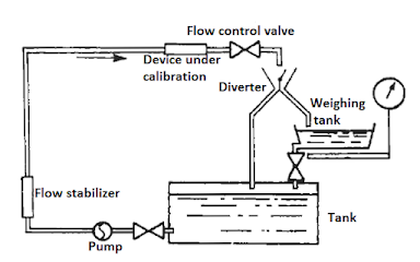
Gravimetric method – where the flow of liquid through the meter being calibrated is diverted into a vessel that can be weighed either continuously or after a predetermined time, the weight of the liquid is compared with the registered reading of the flowmeter being calibrated.

calibrating a flowmeter by weighing
Figure 1.1 calibrating a flowmeter by weighing


Pipe prover – this device also known as a meter prover, consists of a U-shaped length of pipe and a piston or elastic sphere. The flowmeter to be calibrated is installed on the inlet to the prover and the sphere is forced to travel to the length of the pipe by the flowing liquid. Switches are inserted near both ends of the pipe and operate when the spheres passes them. The swept volume of the pipe between the two switches is determined by initial calibration and this known volume is compared with that registered by the flowmeter during calibration.

Don't miss out on key updates, join our newsletter list here.

Thursday, March 16, 2023

The Operation of Linear Variable Differential Transformer (LVDT)

 Linear variable differential transformer (LVDT) is an inductive transducer that is commonly used to translate linear motion into electrical signals.

An illustration of LVDT circuit is shown below:

LVDT

Fig 1.0 LVDT connection circuit

The transformer consists of a single primary winding P and two secondary windings S1 and S2 wound on a cylindrical former. A sinusoidal voltage of amplitude 3 to 15 volt and frequency 50 to 20 kHz is employed to excite the primary winding. The two secondary windings have equal number of turns and are identically placed on either side of the primary winding.

The primary winding is connected to an alternating current source. A movable soft-iron core is placed inside the former. The displacement to be measured is applied to the arm attached to the soft iron core. The core is usually made of high permeability, nickel iron. This is slotted longitudinally to reduce eddy current losses. The assembly is placed in a stainless steel housing to provide electrostatic and electromagnetic shielding. The frequency of ac signal applied to primary winding can be between 50 Hz and 20 kHz.

As the primary winding is excited by an alternating current source, it produces an alternating magnetic field which in turn induces alternating voltages in the two secondary windings.

The output voltage of secondary S1 is ES1 and that of secondary S2 is ES2. In order to convert the outputs from S1 and S2 into a single voltage, the two secondary S1 and S2 are connected in series opposition. The differential output voltage is:

E0 = ES1 – ES2                                                                        

Operation of LVDT

When the core is at its normal (NULL) position, the flux linking with both the secondary windings is equal and hence equal voltages are induced in them. Therefore at null position: ES1 = ES2. Thus, the output voltage E0 is zero at null position.

If the core is moved to the left of the null position, more flux links with S1 and less with winding S2. Correspondingly, output voltages ES1 is greater than ES2. The magnitude of output voltage is thus,

 E0 = ES1 – ES2 and we can say, it is in phase with primary voltage.

In the same way, when the core is moved to the right of the null position ES2 will be more than ES1. Therefore the output voltage 

E0 = ES1 – ES2 and 180° out of phase with primary voltage.

The amount of voltage change in either secondary winding is proportional to the amount of movement of the core. Thus, we have an indication of amount of linear motion. By noticing whether output voltage is increased or decreased, we can determine the direction of motion.

 Related: Transducers and Sensors

Merits of LVDT

  • Output is quite high. Hence, immediate amplification is not necessary.
  • Output voltage is step-less and hence the resolution is very good.
  • The sensitivity is high (about 40 V/mm).
  • It does not load the measured mechanically.
  • Linearity is good up to 5 mm of displacement.
  • It consumes low power and low hysteresis loss.

The Limitations of LVDT

  • It is affected by stray electromagnetic fields. Thus, proper shielding of the device is required.
  • LVDT has large threshold.
  • The ac inputs generate noise.

Don't miss out on key updates, join our newsletter list here.

Wednesday, March 15, 2023

The Principle of Operation of an Electromagnetic Flowmeter

Electromagnetic flowmeters are widely used in industrial process flow measurement. These meters come with several features for example: they offer non-invasive flow measurement, they can measure reverse flows and are insensitive to viscosity, density and flow disturbances. Additionally, electromagnetic flowmeters can respond swiftly to flow changes and are linear devices for a wide range of measurements.

Working Principle of the Electromagnetic Flowmeter

Electromagnetic flowmeter operation is based on Faraday’s law of electromagnetic induction. The induced voltages in an electromagnetic flow meter are linearly proportional to the mean velocity of liquids or to the volumetric flow rates. As in the case in many applications, if the pipe walls are made from non-conducting elements, then the induced voltage is independent of the properties of the fluid.

Faraday’s law of induction states that if a conductor of length l (m) is moving with a velocity v (m/s) perpendicular to a magnetic field of flux density B (Tesla) then the induced voltage (e) across the ends of a conductor can be expressed by:

   e = Blv                                      

This is demonstrated in the figure below:

The operating principle of electromagnetic flowmeter
Figure 1.0 The Operational principle of electromagnetic flowmeter

In the above illustration, the magnetic field, the direction of the movement of the conductor, and the induced emf are all perpendicular to each other.

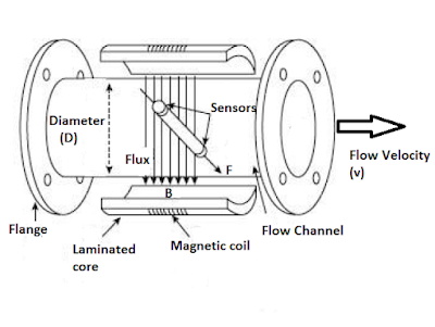
Let’s consider a simplified electromagnetic flowmeter construction below:

Construction of a practical electromagnetic flowmeter

Figure 1.1 Construction of practical electromagnetic flowmeter

The externally located electromagnets create a homogenous magnetic field (B) passing through the pipe and the liquid inside it. When a conducting flowing liquid cuts through the magnetic field, voltage is generated along the liquid path between the two electrodes positioned on the opposite sides of the pipe.

The conductor is the liquid flowing through the pipe, and the length of the conductor is the distance between the two electrodes, which is equal to the tube diameter (D). The velocity of the conductor is proportional to the mean flow velocity (v) of the liquid. Hence, the induced voltage becomes:

  e = BDv

If the magnetic field is constant and the diameter of the pipe is fixed, the magnitude of the induced voltage will be proportional to the velocity of the liquid. If the ends of the conductor, in this case the sensors that are connected to an external circuit, the induced voltage causes a current, i to flow, which can be processed appropriately as a measure of the flow rate.

Electromagnetic flowmeters are often calibrated to determine the volumetric flow of the liquid. The volume of liquid flow Q can be related to the average fluid velocity as:

Q = Av

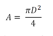
Where A is the area of the pipe, which can be written as:


Pipe Area

That gives the induced voltage as a function of the flow rate:

We know that fluid velocity v = Q/A

We can derive the induced voltage as:


Induced voltage in electromagnetic flowmeter

Equation 1.4 indicates that in a well-designed electromagnetic flowmeter, if all other parameters are kept constant, the induced voltage is linearly proportional to the liquid flow only.

Even though the induced voltage is directly proportional to the mean value of the liquid flow, the main problem in the use of electromagnetic flowmeters is that the amplitude of the induced voltage is small relative to extraneous voltages and noise. The noise sources include:

  • Capacitive coupling between signal and power circuits.
  • Stray voltage in the process liquid.
  • Capacitive coupling in connection leads.
  • Inductive coupling of the magnets within the flowmeter.
  • Electromechanical emf induced in the electrodes and the process fluid.

Key Merits of Electromagnetic Flowmeters

The electromagnetic flowmeters have the following advantages:

  • The output (voltage) is linearly proportional to the input (flow).
  • There is no obstacle to the flow path which may cause reduction in pressure.
  • The electromagnetic flowmeter can measure flow in pipes of any size provided a powerful magnetic field can be produced.
  • The output is not affected by changes in the characteristics of the liquid such as pressure, viscosity, and temperature.
You can also read: Working Principle of Ultrasonic Flowmeter

Shortcomings of Electromagnetic Flowmeters

The electromagnetic flowmeters have the following limitations:

  • The conductivity of the liquid being measured should not be less than 10 μꭥ/m.  It is important to note that most water based/aqueous solutions are adequately conductive while a majority of hydrocarbons solutions are not sufficiently conductive.
  • The operating cost is usually very high in an electromagnetic flowmeter specifically if heavy slurries are handled.
Related resource: Ultimate guide to Industrial flow Instruments

Don't miss out on key updates, join our newsletter list here.


Thursday, August 15, 2019

How a VFD works and when to use it


Did you know you could save on energy consumption and costs by using a VFD? You can also tighten your processes, increase production, reduce maintenance, and extend the life of your equipment.

But what is a VFD, you ask? Let’s take a look.

Defining VFD

VFD stands for variable frequency drive. It’s a motor controller for electric motors. VFDs are also known as adjustable speed drives, adjustable frequency drives, AC drives, microdrives, inverters, and variable speed drives.

The word “frequency” in the name relates to the frequency of the power delivered to the motor, which is measured in hertz. Changing the frequency changes the speed of the motor shaft.  If your electric motor doesn’t need to run at full speed for the entire process, you can save some juice and some wear and tear by installing a VFD to vary the speed of the motor.

A variable frequency drive can also get a motor started and ramp it up to speed at a controlled acceleration rate. This makes the start-up smooth, while also saving on electricity and motor life.

A VFD allows one motor to be used for processes that may require or allow different speeds.
Variable Speed Drive in Operation
Variable Speed Drive


How Does a VFD Operate?

A VFD converts fixed frequency AC line voltage to DC, then makes new AC at whatever voltage and frequency are needed to run the motor at the desired speed. The VFD consists of a converter section, a filter section, an inverter section and control section. 
  • The Control section operates the entire VFD, monitors the VFD and motor for safe operation, and interact with the machine operator or automation control system. 
  • The Converter uses diodes and/or SCRs to change AC utility power to DC
  • The Filter ''Cleans'' the DC power with inductors and capacitors
  • The Inverter makes new AC power for the motor using transistors as switches

Those switches are what allow the VFD to function at different speeds. The transistorized switches let the VFD adjust the frequency and voltage of the power supplied to the motor. As the frequency changes, so does the motor speed.

What’s It For?

Anytime you have a system run by an AC electric motor, you may have a need for a VFD. For example, a common use is controlling the speed of a water pump. If the pump is part of a water treatment process, a low demand for water can mean that the water doesn’t exit the plant at the same speed it enters for treatment.

To slow down the supply-side, a VFD is used to slow the water pump.

As mentioned before, a VFD can be used to get a motor started and smoothly accelerate it to operating speed. Energy usage is reduced if operating speed is below full speed.  There is less strain on the motor, less wear and tear on the machinery, and it doesn't just start with a jolt. Using VFDs on conveyors and belts eliminates those jerky starts and increases throughput without damaging equipment.

VFDs can be regulated with a PLC instead of manual adjustment. It’s an easy way to automate a repetitive task and reduce labor cost.

A VFD is a handy little gadget that can help you tighten your process controls, increase production, and minimize mistakes. Your maintenance and repair needs go down, and so does your electricity bill. At the end of the shift, your company has made a little more money than it did before.
You can also read: 


Don't miss out on key updates, join our newsletter list here.
About the Author:
With over 25 years of experience in the industrial automation repair industry, Jeff Conner is the Dallas Service Manager for Control Concepts and serves on the Advisory Committee for the Electronics Technologies Department at Texas State Technical College.
Control Concepts helps design, fabricate, install, test, and program control systems. They service almost any brand of control found in automated systems and can send an experienced technician anywhere, wherever one is needed 24 hours a day, 7 days a week.

Monday, July 29, 2019

Why you should modernize your Relay Control System with a PLC

If you are still running a hard-wired relay control system, it may be time to consider modernizing with programmable logic controllers, or PLCs. PLCs have gotten smaller and more efficient over the years, and they can replace a complex relay system and provide a host of benefits.


Defining PLCs

A programmable logic controller is what it sounds like - a small, special-use computerized control device used in industrial systems. It handles sequential controls, counters, timers, and more. PLCs are more widely used than special-purpose digital computers and have found a place in industrial manufacturing and civil applications.

A PLC continuously monitors input values from sensors, operator controls, etc. and produces outputs to operate machinery based on programming.

How Does a PLC Work?

A PLC is made up of a CPU module, a power supply, and one or more I/O modules. There is no hard drive since the program is stored in internal memory.  A touch screen or other HMI (Human Machine Interface) is optional. The PLC stays inside a control panel and uncomplainingly does its job.

It performs several steps as part of a typical scan cycle:

  • Cycles the operating system and monitors time
  • Reads data from the input module and checks all input statuses
  • Executes user or application program
  • Performs all internal diagnostics and communication tasks
  • Writes data into the output module

As long as the PLC is on, it repeats the cycle until the programming or process comes to an end.
Programmable Logic Controllers


The Benefits of PLCs

One benefit has already been mentioned. A PLC is used across multiple industries and in smaller machinery. But there are other benefits as well. PLCs are:

  • Robust and durable
  • Easy to program
  • Reliable 
  • Easy to use

The I/O module doesn’t even need to be near the CPU. They can be miles apart and still operate connected by data cables. Your PLC isn’t stuck to a single cabinet or building. A PLC can have more than just digital inputs & relay outputs. Improvements over the years have given PLCs the ability to work with a wide variety of analog signals as well as Ethernet and serial communications protocols.

PLCs give your production lines flexibility that you don't get with relays. If you need to retool your line, you can easily reprogram your PLCs to handle the new process.

PLCs are found in such industries as chemical, automotive, steel, food/beverage and more.

Why you should modernize your Relay Control Systems with a PLC

As you have probably experienced, relays use a ton of electricity. They take up space, and they’re noisy and tend to fail a lot. All those electrical connections between relay & socket & interconnecting wires mean more downtime for maintenance. Mechanical relay systems fail more often than PLCs.

If all you need to do is turn an electrical motor on and off safely, a relay may be all you need. But most industrial processes today involve more than that. You need something modern and smart to make your processes energy-efficient and cost-effective.

Modern industry leverages the power of the computer revolution to improve almost every step of any process. Modernize your relay control systems with a PLC, and you'll wonder why it took you so long.

About the Author:

With over 25 years of experience in the industrial automation repair industry, Jeff Conner is the Dallas Service Manager for Control Concepts and serves on the Advisory Committee for the Electronics Technologies Department at Texas State Technical College.

Control Concepts helps design, fabricate, install, test, and program control systems. They service almost any brand of control found in automated systems and can send an experienced technician anywhere one is needed 24 hours a day, 7 days a week.

Friday, May 3, 2019

Turning Fork Level Switches

This level switch uses a metal tuning fork structure to detect the presence of a liquid or solid (powder or granules) in a vessel.
Turning Fork Level Switch
An electronic circuit continuously excites the tuning fork, causing it to mechanically vibrate. When the prongs of the fork contact anything with substantial mass, the resonant frequency of the structure dramatically decreases. The circuit detects this change and indicates the presence of material contacting the fork. The fork’s vibrating motion tends to shake off any accumulated material such that this style of level switch tends to be resistant to fouling.
You can also read: Ultrasonic Level Switches
Don't miss out on key updates, join our newsletter list here.

Tuesday, March 19, 2019

Types of Signal Converters Commonly used in Industrial Control


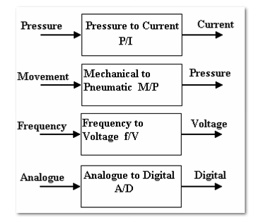
Signal converters change a signal from one form to another. In most cases, we have standard inputs and output ranges.
Types of signal converters

Most signal converters have two adjustments-zero and range.
Examples of Signal converters
Nozzle-flapper and differential pressure cells
The nozzle-flapper system is widely used in D.P. Cells. An example is shown below, that converts differential pressure (e.g. from a differential Pressure flow meter into a standard pneumatic signal). This is widely used in the control of air operated pipeline valves.
Flapper Nozzle System

The bellows respond to the differential pressure and moves the lever. This moves the flapper towards or a way from the nozzle. The air supply passes through a restrictor and leaks out of the nozzle. The output pressure hence depends on how close the flapper is to the end of the nozzle. The range of the instrument is adjusted by moving the pivot and zero position is adjusted by moving the relative position of the flapper and nozzle. This system is used in a variety of forms. Instead of bellows, a bourdon tube might be used and this is operated by an expansion type temperature sensor to produce a temperature-pneumatic signal converter.
Current/Pressure conversion 
The figures below show typical units for converting 4-20 mA into 0.2-1 bar or 3-15 psi. They contain adjustments for range and zero. They are widely used for converting the standard pneumatic and electric signals back and forth. They can also be adjusted to work with non standard inputs to convert them into a standard form.
Current to Pressure Converter (C/P)
Current to Pressure Converter

Pressure to Current Converter (P/C)
Pressure to Current Converter

Electric D.P. Cells
They provide the same functions as the pneumatic versions but they are given an output of 4-20 mA using electrical pressure transducers. They are typically used with D.P. Flow meters.
Differential Pressure Transmitter

Analogue -Digital Converters
Analogue to digital conversion is a process of turning an analogue voltage or current into a digital pattern which can read by a computer and processed, this is done by analogue -digital converters.  Lets look at the Binary Numbers, a number may be represented in digital form by simply setting a pattern of voltages on a line high or low. It is normal to use 4, 8, 16 or 32 lines. An 8 bit binary pattern is shown in the below figure:
Binary Numbers
The total pattern is called a word and the one above is an 8 bit word. The pattern may be stored in an 8 bit register. A register is a temporary store where the word may be manipulated. The Bit zero is called the least significant bit (LSB) and the bit with highest value is called the most significant bit (MSB). Each bit has a value of zero when off (LOW) or the value shown when on (HIGH). The maximum value for an 8 bit word is 255.
Digital to Analogue Converters
These are devices for converting a binary number into an analogue voltage. The change in the binary value from zero to a maximum corresponds with a change in the analogue value from 0 to maximum.
One of the manufacturers of signal converters is Omega.
Don't miss out on key updates, join our newsletter list here.